EasyManua.ls Logo

Elegoo Neptune User Manual

Elegoo Neptune
2 pages
To Next Page IconTo Next Page
Page #1 background imageLoading...
Page #1 background image
Notice Before First Use
1. Power Supp ly Voltage Selection:
l Please a djust the voltage to match your local
voltage be fore first use, switc h to 115V (for
operation 100-120 V) , or to 2 30V (for ope ration 22 0-
240V).(The default fa ctory voltage setting is 230V
Please r efer to the included USB Drive for a Setup and Insta llation Ins tructional Video.
Voltage Requirements for some countries:
①CA/US/JP:100-120V
②DE/FR/UK/AU/RU/IT/ES: 220-240V
l The Y-ax is slider plate is adjuste d at the factory, but the machin e's pulle ys may be loose due to trans portation. If
the printi ng platform is shak y or loose, you can us e an open -end wre nch to slowl y unscrew the hexagon al isolati on
column unde r the pla tform unti l the Y-a xis slide r plate slides s moothly with out shakin g!
l Similarly, you can adj ust the he xagonal is olation colum n undern eath the p rint head if it bec omes wobb le or loos e.
There ar e also cor respondin g isolation columns for the pulle ys on both sides of t he gantry that can b e adjuste d.
2. Y-Axis Slid er P late Wobble:
Question and Answer IconNeed help?

Do you have a question about the Elegoo Neptune and is the answer not in the manual?

Elegoo Neptune Specifications

General IconGeneral
Nozzle Diameter0.4 mm
Filament Diameter1.75 mm
Printing TechnologyFDM (Fused Deposition Modeling)
Bed LevelingManual
Supported MaterialsPLA, ABS, TPU
Bed TemperatureUp to 100°C
ConnectivitySD Card, USB
Power Supply24V
Print Speed60-100 mm/s

Summary

Power Supply Voltage Selection

Voltage Requirements by Country

Lists voltage requirements for specific countries like CA/US/JP (100-120V) and DE/FR/UK/AU/RU/IT/ES (220-240V).

Y-Axis Slider Plate Wobble Adjustment

Troubleshooting Slider Plate Wobble

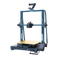
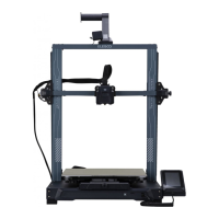
Guidance on adjusting hexagonal isolation columns under the platform and print head to resolve wobble or shaking.

Auto-Leveling Procedure

Initial Leveling Setup

Calibrate distance between nozzle and platform using an A4 paper, adjusting height compensation for center point calibration.

Auxiliary and Automatic Calibration

Perform manual auxiliary leveling on corners, then initiate automatic calibration with heating and 36-point scanning.

Z-Axis Compensation Setting

Finalize leveling by adjusting Z-axis compensation with an A4 paper until it's snug but can be pulled out.

Related product manuals