18
EN
Instruction manual
PS 2000 B Triple Series
Date: 11-13-2019
Operating the device
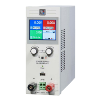
3.2 Controls & sockets
Power switch
This is used to switch the device completely on or o.
Pushbuttons „Preset“
These buttons are used to switch the actual values dis-
play to set values display. It is also used to activate the
control panel lock. See sections 4.4 and 4.5 for details.
Displays
These blue LCDs present all information at one glance.
Knobs „Voltage“
These knobs are used to adjust the voltage of the
outputs 1 and 2 or, in preset mode, to adjust the OVP
threshold.
Mini USB socket
Here the device is connected to a PC, in order to
monitor, remotely control or update the device. See
section 6.5.
Knobs „Current“
These knobs are used to adjust the current of the
outputs 1 and 2 or, in preset mode, to adjust the OCP
threshold.
Pushbuttons„On/O“
Are used to switch the outputs 1 and 2 on or o.
Power output 1, safety sockets, poled
The sockets can be used to plug 4mm open or safety
Bueschel plugs. The left-hand control panel is dedi-
cated to control this output.
Power output 2, safety sockets, poled
The sockets can be used to plug 4mm open or safety
Bueschel plugs. The right-hand control panel is dedi-
cated to control this output.
Auxiliary output 3, safety sockets, poled
The sockets can be used to plug 4mm open or safety
Bueschel plugs. This output can only be adjusted by
voltage and only via a trimmer which is located behind
the hole between the output sockets.
Pushbutton „Tracking“
This button used to activate or deactivate the tracking
mode. See section „4.6 Tracking mode“ for details.
Grounding socket
This socket can be used to plug 4mm open or safety
Bueschel plugs and is connected to the enclosure. It
can used to ground a connected load.
4. Handling
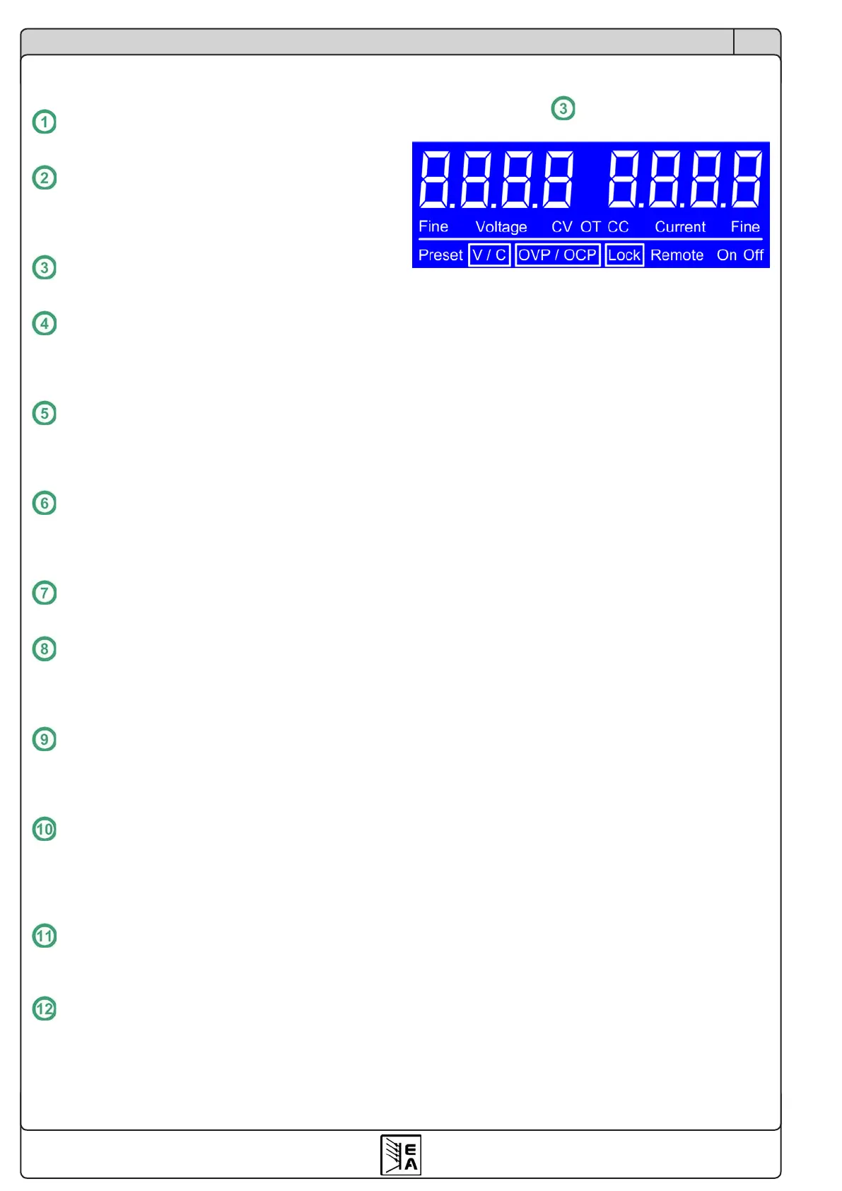
4.1 The display
Figure 3
4.1.1 Status tokens
The status tokens in the display indicate following:
CV - Voltage regulation active (only if output is „on“)
CC - Current regulation active (only if output is „on“)
Preset V/C - Set value display of voltage/current active
Preset OVP/OCP - Set value display of OVP/OCP active
OT - Overtemperature error
OCP - Overcurrent protection
OVP - Overvoltage protection
Remote - Remote control active (via USB)
Lock - Control panel lock active
Fine - Indicates activated ne adjustment mode
4.1.2 Error indication
If an error like overvoltage, overcurrent or overtemperature
occurs it is displayed in one of the LCDs by the text „Error“
and a token (OT, OCP, OVP) and the output voltage is
cut o. The text remains in the display until the user has
acknowledged the error with the „On/O“ button, which will
also switch the output o.
After an overtemperature error, the output voltage will return
automatically and „Error“ will be cleared, unless the output
has been switched o by the user meanwhile. Other errors
require the user to switch the output on again, in order to
continue working with the device.
Other display elements are connected to certain operation
modes and are explained in the following sections.
The main outputs 1 and 2 are working separately, so in case
of an error the other output will continue working. Output 3
does not cause any error indication.

 Loading...