21
Instruction manual
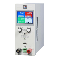
PS 2000 B Triple Series
EN
Date: 11-13-2019
5. Behavior of the device
5.1 Switching on by power switch
The power switch is located at the front. After the device
is started, following situation will be set:
• The outputs are o
• The set values are restored, adjustment mode is reset
to coarse
• Any condition like REMOTE, LOCK or TRACKING is
reset.
5.2 Overvoltage
An overvoltage error can occur due to an internal defect
(output voltage rises uncontrolled) or by a too high voltage
from external. The overvoltage protection (OVP) will switch
o the voltage of the corresponding output (main output 1
or 2 only) and indicate the error in the display by the text
„Error“. This error has to be acknowledged rst by the On/
O pushbutton. Then the display will change to normal
display again. Also see section 4.2.2.
External voltages higher than 120% nominal voltage
at the output must be avoided, or else internal compo-
nents of the device might be destroyed!
If the cause of the overvoltage is removed, the output can
be switched on again.
In parallel connection of the main outputs 1 and 2, the
output voltage of one output can cause an OV error on the
other output if the OVP threshold of the eected output is
set lower. In such a case it is recommended to either adjust
the OVP thresholds of both outputs to the same value or to
use tracking mode, which will handle this matter.
5.3 Overtemperature
If the unlikely event of an overtemperature (OT) error occurs
by internal overheating, the voltage of the corresponding
output is cut o and the status token „OT“ is shown in the
related display, together with the text „Error“. The output
will automatically switch on again after the unit has cooled
down. In case this is not wanted, the output can be manually
switched o during the overtemperature period.
5.4 Overcurrent
The device can react in two dierent ways to overload
resp. overcurrent:
1. By switching the corresponding output o (OCP) or
2. By limiting the output current (CC)
In order to switch the output o, it is required to adjust the
OCP threshold (see section 4.4) to lower than the current
limitation, because else the current is just limited.
Operating the device
6. Other applications
6.1 Series connection of outputs 1 & 2
The main outputs 1 and 2 can be connected in series in
order to gain a higher output voltage. Following applies:
• There will be no totals formation of the total output voltage
on any display
• The total voltage is the sum of the single output voltages
• The maximum current is limited to the lowest adjusted
current of both outputs. It means, if one output is set to
0A, the unit will not put out voltage and no current during
series connection
It is recommended to use tracking mode (see 4.6), in order
to have the adjusted voltage and current at identical values.
Series connection of any or both main outputs 1
and 2 with output 3 is not allowed!
6.2 Series connection of several units
Several units of preferably same type, but at least with
identical nominal current, can be connected in series in
order to gain a higher total output voltage.
To do so, the positive DC output of one unit is connected to
the negative DC output of the next unit etc. The positive DC
output of the last unit will then be the positive output of the
whole series connection and will have the high potential.
Because of safety and insulation reasons it is not al-
lowed to connect an arbitrary number of unit in series. The
DC minus pole (black) of any output on any unit must not
have a potential of higher than 300V DC against ground
The maximum allowed series connection voltage is 342V
DC for 42V models and 384V DC for 84V models. Special
safety measures are required when working with such
high voltages!
If units with dierent nominal current are connected in
series, the unit with the lowest nominal current will deter-
mine the maximum current of the system.
In a series connection, only the positive or negative
DC output of the rst unit (the one with the lowest potential)
may be grounded.
6.3 Parallel connection of outputs 1 & 2
The main outputs 1 and 2 can be connected in parallel in
order to gain a higher output current. Following applies:
• There will be no totals formation of the total output current
on any display
• The total current builds from the output current of the
single outputs
It is recommended to use tracking mode (see ), in order to
have the adjusted voltage and current at identical values.
In parallel connection of the main outputs 1 and 2, the
output voltage of one output can cause an OV error on the
other output. See section 5.2 for details.

 Loading...