Page 41
EA Elektro-Automatik GmbH
Helmholtzstr. 31-33 • 41747 Viersen
Germany
Fon: +49 2162 / 3785-0
Fax: +49 2162 / 16230
www.elektroautomatik.de
ea1974@elektroautomatik.de
PS 9000 T Series
3.4.3.1 Menu “Settings”
This is main menu for all settings related to the general operation of the device and of the interface(s).
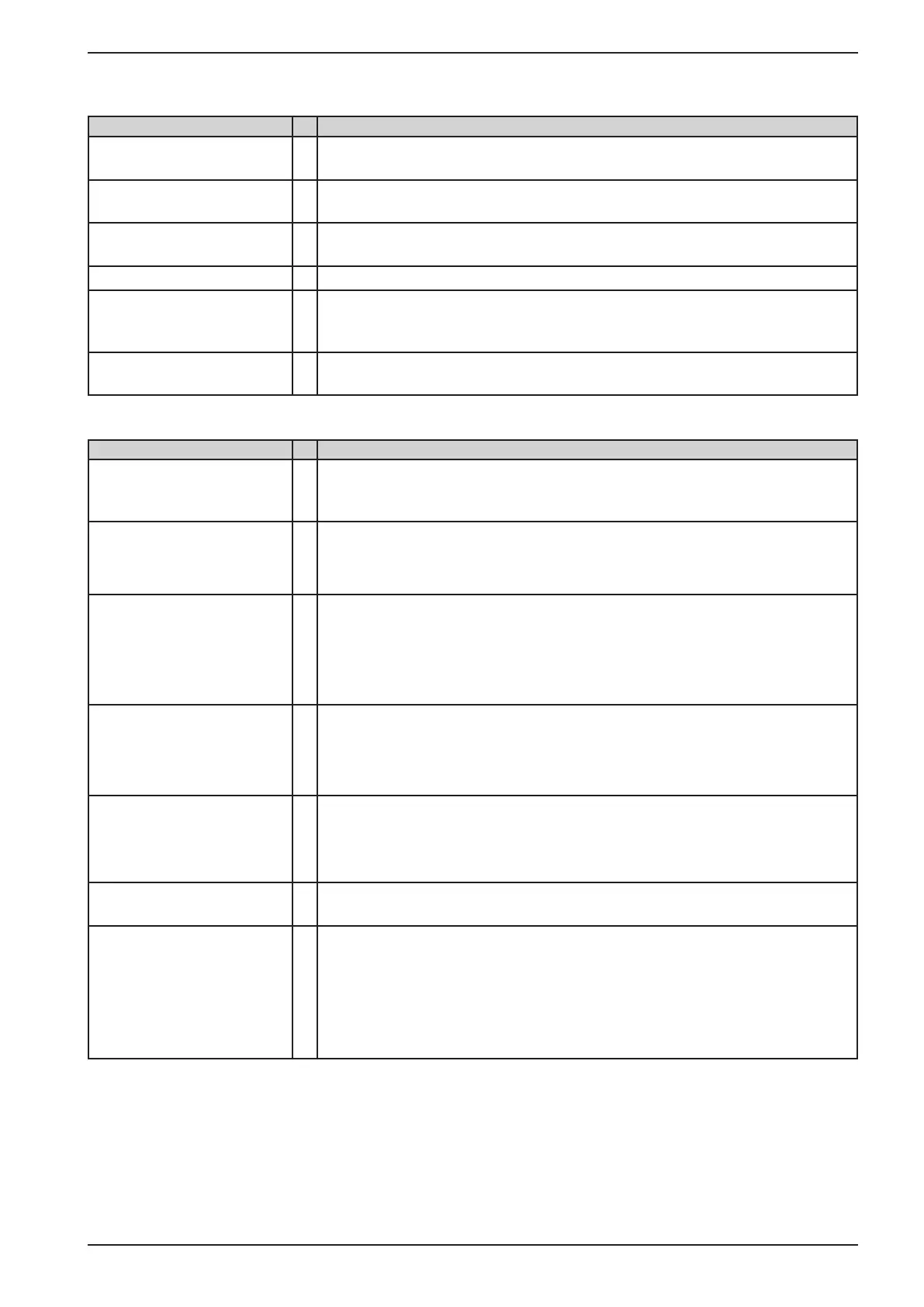
Sub menu P. Description
Output Settings 1 Allows for adjustment of set values related to the DC output, alternatively to the
handling in the main screen of the display
Protection 1 Allows for adjustment of protection thresholds (here: OVP, OCP, OPP) related
to the DC output. Also see section „3.3. Alarm conditions“
Limit Settings 1 Allows for adjustment of adjustment limits for set values. Also see section „3.4.4.
Adjustment limits (Limits)“
General Settings 1 Settings for the operation of the device and its interface(s). Details below
Reset device 2 Touch area “Start”willinitiatearesetofallsettings(HMI,proleetc.)todefault
values, as shown in the menu structure diagrams on the previous pages, and
all set values to 0
Calibrate device 2 Touch area “Start” starts a calibration routine (see „4.3. Calibration“), but only
if the device is in U/I/P mode, i.e. R mode not activated.
3.4.3.2 Menu “General Settings”
Setting P. Description
Allow remote control 1 Selection “NO” means that the device cannot be remotely controlled over either
the digital or analog interfaces. If remote control is not allowed, the status will be
shown as “local” in the status area on the main display. See also section 1.9.5.1
DC output after power ON 1 Determines the condition of the DC output after power-up.
• OFF = DC output is always off after switching on the device.
• Restore = DC output condition will be restored to the condition prior to switch off.
DC output after PF alarm 2 Determines how the DC output shall react after a power fail (PF) alarm has
occurred:
• OFF= DC output will be switched off and remain until user action
• Auto ON = DC output will switch on again after the PF alarm cause is gone
and if it was switched on before the alarm occurred
DC output after remote 3 Determines the condition of the DC output after leaving remote control either
manually or by command.
• OFF = DC output will be always off when switching from remote to manual
• AUTO = DC output will keep the last condition
USB le separator format 4 SwitchesthedecimalpointformatofvaluesandalsotheCSVleseparatorfor
USBloggingandforotherfeatureswhereCSVlecanbeloaded
US=Commaseparator(USstandardforCSVles)
Default=Semicolonseparator(german/europeanstandardforCSVles)
USB logging with units
(V,A,W)
4 CSVlesgeneratedfromUSBloggingbydefaultaddphysicalunitstovalues.
This can be deactivated by setting this option to “No”
Analog interface range 5 Selects the voltage range for the analog set input values, actual output values
and reference voltage output.
• 0...5 V = Range is 0...100% set /actual values, reference voltage 5 V
• 0...10 V = Range is 0...100% set /actual values, reference voltage 10 V
See also section „3.5.4 Remote control via the analog interface (AI)“ on page
50
 Loading...