102
Page
INSTALLATION INSTRUCTIONS
LOCATION
Select a location where the fire can be supervised during
operation. An electrical isolation switch must be fitted
at the appliance or on an adjacent wall to allow for
emergency shutdown and maintenance. Installation must
meet Australian gas codes AS5601
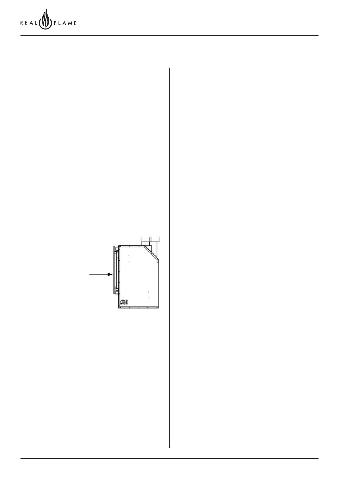
INSTALLATION CLEARANCES
Clearances from combustible materials
Floor 0mm
Sides 25mm
Top 25mm
Flue outer 25mm
Front 25mm
Back 25mm
Note: Once installed no combustible items should be
placed within 600mm of the fire viewing window.
GAS CONNECTION 15mm (1/2”) Compression union
ELECTRICAL CONNECTION 3 Pin 10 Amp GPO plug
POWER RATING OF APPLIANCE 230V 50Hz 0.55 Amp
INSTALLATION CODES
Note appliance gas type – Natural gas/LPG. Should the
appliance be the incorrect gas type, please contact the
supplier for conversion details.
Installers – Please ensure the installation and instruction
manuals supplied with this appliance are supplied to the
customer and the customer is trained on how to operate
the appliance correctly.
Do not modify the appliance.
Do not exceed maximum rated pressures.
Appliance must be installed with gas installation code
(AS/NZS5601.1-2013) and applicable electrical
installation code (AS3000).
Test for gas leaks prior to operating appliance.
Check gas pressures and adjust if incorrect.
FLUE CONFIGURATIONS
0-5m- Aluminum flexi flue as per 0-5m IOM.
5-9m- Aluminum flexi flue insulated. Refer to 5-9m
insulated flue run IOM.
9-13.5m- Poly flue system. Refer to 9-13.5m flue
configuration.
Where lengths greater than 5m are required the inlet is
run completely in aluminum flexible flue, the first 5m of
the outlet flue is run in flexible aluminum flue, then a poly
flue system is used that requires drainage points to waste
for condensation removal. – Note drain fall direction
is different for rooftop flues. – Refer 9-13.5m Rooftop
instruction.
Aluminum flue connections must be sealed with a suitable
sealant.
Recommended Silicon – Non-acetic, neutral cure
150degc or higher temperature rated.
Bostik RTV 926 or similar
Run air intake flue as required – Maximum run 14m. Flues
can be run next to each other.
Maintain clearances to combustibles.
Cladding between trim
and firebox must be non-
combustible materials