29
Page
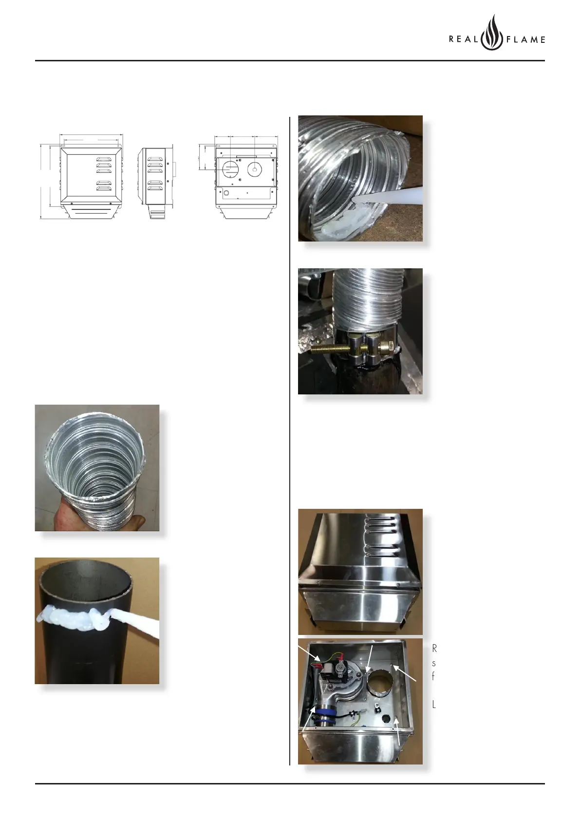
EXTERNAL WALL MOUNTED FAN MODULE INSTALLATION
1. Wall mounted fan module – terminal must be installed
with clearances as specified by AS5601.1 Clause
6.9.3.
2. Run exhaust flue and air intake flue as required
Maximum run 5m. Flues can be run next to each other.
Maintain clearances to combustibles.3 .
3. Connection to appliance
4. Repeat above with air intake flue pipe to heater
connection.
5. Clip flues as required to provide adequate support.
6. Connection to wall mounted fan terminal.
Cut tube to length where
required.
Ensure ends are burr free
and round, test fit flue will
slide over connection.
Apply an 8mm silicon
bead fully around the
inside of the flue end
(heater connection end)
Fit flue clamp over flue
(loosely).
Recommended Silicon
– Non-acetic, neutral
cure 150°C or higher
temperature rated.
Bostik RTV 926 or similar.
Apply an 8mm thick silicon
bead fully around heater
connection approx. 10mm
from the top.
Slide flue onto connection
spigot fully.
Tighten clamp fully.
Wipe excess silicon,
visually check connection
to ensure connection is
fully sealed
Remove cover from fan
terminal
Remove main assembly
from the rear wall
mounting plate assembly.
Remove the 5 screws as
shown. (Do not remove
fan plate screws)
Lift off main fan terminal
assembly.
325
80 125 12 0
382
12 8
12 0
310
280