39
Page
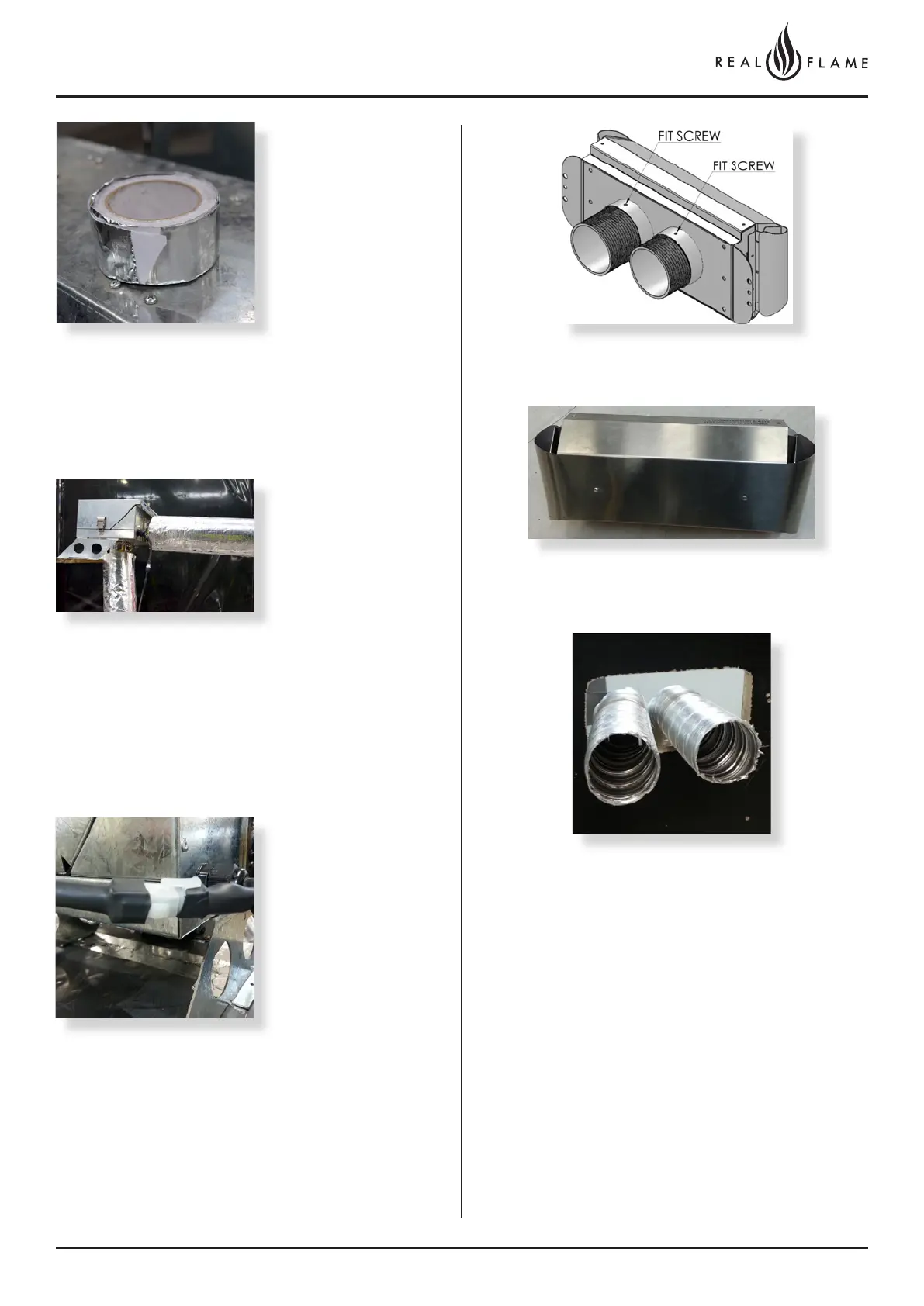
Joins can be taped
together using aluminum
foil self adhesive tape.
Insulation may be fitted
prior and after the inline
powerflue fan.
Failure to fit insulation on the exhaust flue may result in
condensation failures with the appliance.
6. Connect power
lead to fan module.
Ensure lead is clipped
to support where
required.
Do not use connection to
support lead.
Connection to wall terminal
Loose fit connections (wall termination connections)
Locate terminal on wall and predrill mounting holes where
required.
Cut flue exhaust tube (hot tube) to length (Flue must
extend a minimum of 50mm past the exit face of wall.) It
is recommended that the tubes are cut slightly longer and
pushed back into wall upon fixing of wall terminal. Allow
flue movement between terminal and last flue hanging
clip.
Cut Air intake as per flue exhaust.
Ensure ends are burr free and round, test fit flue will slide
inside both the hot exhaust connection and air intake
connection.
Insulation to be run for the first 3m from the appliance. For
flue runs shorter than 3m, insulation is not required.