4
GeneralInstrucons
InialSetup
Before your diagnosc unit is used for the rst me, enter your desired
sengs. These may be readjusted at any me.
1. Acvate the unit by pressing the buon. Once acvated, the LCD
segments will ash and return to the mode last used.
2. Press and hold the buon for 1 second placing the unit in
volume adjustment mode as indicated by the ashing icon. Use the
buons to adjust the volume.
3. Momentarily pressing the buon again places you in sound
adjustment mode. Adjust to the desired mode using the buons.
A chart laying out each sound mode follows this secon.
4. Pressing the buon again allows you to adjust the Satellite
Display brightness as indicated by the ashing number in the display’s
upper right corner. Use the buons to adjust the brightness level.
Note: Level “0” turns the Satellite Display o.
5. The setup feature will meout aer ve seconds of inacvity and the
unit is ready for use.
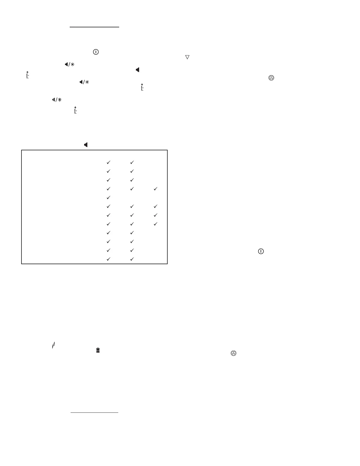
SoundModeOpons
The number to the right of the symbol indicates the sound mode.
Unit powered on Mode1 Mode2 Mode3
Elementsnetworkconnecon
Change VS/AL mode
Changeaudiosengs
Baerylow
Incrementalapexsteps(.1mm)
Close to apex (< .5mm)
At apex
Past apex
Vitality-circuitcompleted
Vitality-circuitbroken
Vitality-increase(each10steps)
Vitality - maximum
DevicePowerO
The unit will turn o aer 60 seconds of non-use.
Satellite Display
Note:TheSatelliteDisplayisnotautoclavable
A revoluonary Satellite Display is included with your diagnosc unit
which gives a quick indicaon of the distance to the apex in AL mode
and output level in VS mode. Use the strap provided to aach your
Satellite Display to a chair, paent bib or microscope for ergonomic
monitoring of status.
Power Symbols
When the unit receives power from a wall outlet or the Elements Bus
Connector, the symbol appears in the lower right corner of its display.
When running on baery power, the symbol appears. The diagnosc
unit uses a rechargeable baery pack and can be used while charging.
As baery strength is depleted, segments of the baery meter indicate
remaining capacity. When the last segment of the baery meter begins
to blink, recharge the unit immediately by plugging it into a wall outlet.
Failure to do so can result in inaccurate readings. To maximize life, the
baery pack should be fully discharged before each recharge. Should
the baery pack require replacement, use only the pack expressly
for this unit from SybronEndo (973-0305). There are no other user
serviceable items within the unit.
ApexLocatorMode
NumericDisplay
The Numeric Display shows distance to the apical foramen from
+3.0 mm to – 0.5 mm in 0.1 mm increments. Please contact your
sales representave for informaon regarding the accuracy of the
measurement. Beyond 1.5 mm from the foramen, readings are less
reliable. When a le reaches the apical foramen, the numeric display
will read “0.0”. If the le has gone past the foramen, the display exhibits
a negave number down to “-0.5.”
GraphicDisplay
The display imitates your le moving toward the apex while its depth is
indicated on the bar to the right. Upon coronal movement of the le,
a remains for 15 seconds at the greatest depth reached near the
apex. Upon reaching the apical foramen, the hollow le solidies and
the black “Apex” bar appears. If the le goes beyond the foramen, this
bar will blink. The le should then be withdrawn approximately 0.5mm
to reach the constricture. Segments of the symbol will indicate you
are nearing the correct posion. Upon reaching the constricture, the
segments of the constricture symbol will ash.
Satellite Display
The Satellite Display mirrors the Graphic Display. LED lights illuminate as
the le progresses within the canal. Each segment represents 0.2mm.
For example, when a le progresses from 0.4mm (from the apical
foramen) to 0.3mm, the representave LED will illuminate dimly and
then brightly upon reaching 0.2mm. When the foramen is encountered,
the boom green LED mimicking the “Apex” bar on the Graphic display
will acvate. If the le goes past the apical foramen, the LED’s at the top
and boom of the satellite will ash alternately.
Aer reaching the foramen, the le is withdrawn 0.5mm to the
constricture whereupon the representave segment turns green.
ApexLocatorDireconsForUse
NOTE: The Apex Locator should be used only as an adjunct to normal
endodonc procedures. While the unit can reduce the number of
radiographs necessary, an inial radiograph must be taken to esmate
working length. Clinical judgment, including knowledge of root canal
anatomy, is paramount when interpreng results.
1. Grasping the Satellite Cord plug by its knurled secon, line up the
red dots and gently push it into its receptacle at the front of the
unit. The cord may only be plugged in or removed by pulling the
knurled secon of the plug.
2. Place the Paent Lead Cord connector into the Satellite Cord
receptacle.
3. Insert either the Bifurcated Probe or File Clip into the Paent Lead
Cord receptacle.
4. Power the unit by depressing the buon.
5. Ensure the unit reads “apex” in the upper right hand corner
conrming the unit is in Apex Locator mode. If not, press the buon
to do so.
6. Place the lip clip on the paent’s lip. Direct contact between the
mucosa and the lip clip must be made for proper funcon.
7. Ensure the unit is funconing properly by touching the Probe p to
the gingiva. You should noce a change in the display.
8. Touch the Bifurcated Probe or connect the File Clip to an
endodonc le that is in the canal.
9. Upon contact, the Numeric Display and small bar underneath it will
appear unl contact is broken.
10. Work the le apically unl the Numeric Display reads “0.0”, the
Graphical Display exhibits a solid le, and the black “apex” bar
appears. Note: The unit is sensive and responds to minute changes
in le posion.
11. Pull back approximately 0.5mm to reach the constricture. As you do
so, segments of the will appear. The complete symbol will ash
at the constricture.
12. Set the desired working length by adjusng the posion of the le
stop.
13. When contact is broken, the Numeric Display will show two dashes
and the le icon will disappear.
ApexLocatorTroubleshoong
To correct errac measurements:
• Ensure the lip clip fully contacts the paent’s mucosa.
• Check all connecons.
• Verify the unit turns on automacally when a circuit is completed.
Dry the canal with a paper point to increase accuracy when:
• Excessive conducve uids form a conducve bridge between
canals or with a metallic restoraon or crown.
 Loading...