18 Product description
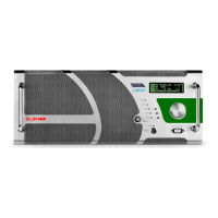
1 GRILL - ventilation grille.
2 DISPLAY - display showing the operating parameters and selected functions using the
encoder.
3 ENCODER - multifunction knob allowing navigation through the function menus and
modification of the operating parameters.
4 KEY SELECTOR - it can be set to LOCAL (controllable through the front panel) or REMO-
TE (controllable via PC) mode, by turning the key supplied with the equipment.
5 WARNING LIGHTS - LED list:
• FAULT (red) _ this warning light is on when the equipment is considered to be in
“FAILURE”;
• ON AIR (green) _ this warning light is on when the apparatus is broadcasting;
• ST-BY (yellow) _ this warning light is on when the apparatus is not broadcasting;
• LOCAL (blue) _ this warning light is on during local programming;
• MAINS (green) _ this warning light is on when power is supplied.
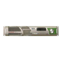
6 INTERFACE - B9 F connector for connection with telemetry according to the EIA485
standard, or to a PC.
7 RF MONITOR - BNC connector for connection with external measurement tools, al-
lowing to the RF signal to be taken at a low level (0dBm at scale bottom). This monitor
is not calibrated, therefore it is not guaranteed that the output level stays constant as
frequency changes. It CANNOT be used for measuring the output power, or for measu-
ring the harmonic components.
9 PROGRAMMING LEVER – Located on the right hand side of the panel facing the ma-
chine. It can be moved by means of a flat screwdriver upwards (in running mode) and
downwards (in program mode).
9 VDE - VDE socket for the equipment power supply.
10 EXCITER DUMMY LOAD - N connector for internal unbalanced load input.
11 RF IN - two N connectors for modulator RF inputs.
12 RF OUT - N connector for RF splitter output.
13 DUMMY LOAD - N connector for reserve exciter load.
14 PROFILES - DB25 F connector. Normally unused. It is used for the selection of profiles
stored (in the case of apparatus as a reserve).
15 TC/TS - DB25 F connector for remote control and remote telesignalling.
16 MASTER - DB25 F connector for interface with amplifiers and modulators.
17 SLAVE - unused connector.
18 INTERLOCK - unused connector.
19 IEEE485 - DB9 F connector for connection with telemetry according to the EIA485
standard.
20 AUX 1 - DB9 F connector for environment temperature probe.
21 FWD- BCN connector for forward power input.
22 REF - BNC connector for reflected power input.
23 MONITOR - BNC connector for low level signal input in antenna.
24 DUMMY LOAD - DB9 F connector for unbalanced load connection.
25 PWS DUMMY LOAD - 3W3 connector for the unbalanced load fan power supply.
26 PWS COMBINER - 3W3 connector for combiner fan power supply.
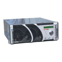
27 FAN - cooling fans. There are two, 12-28Vdc, 306M3/h max.