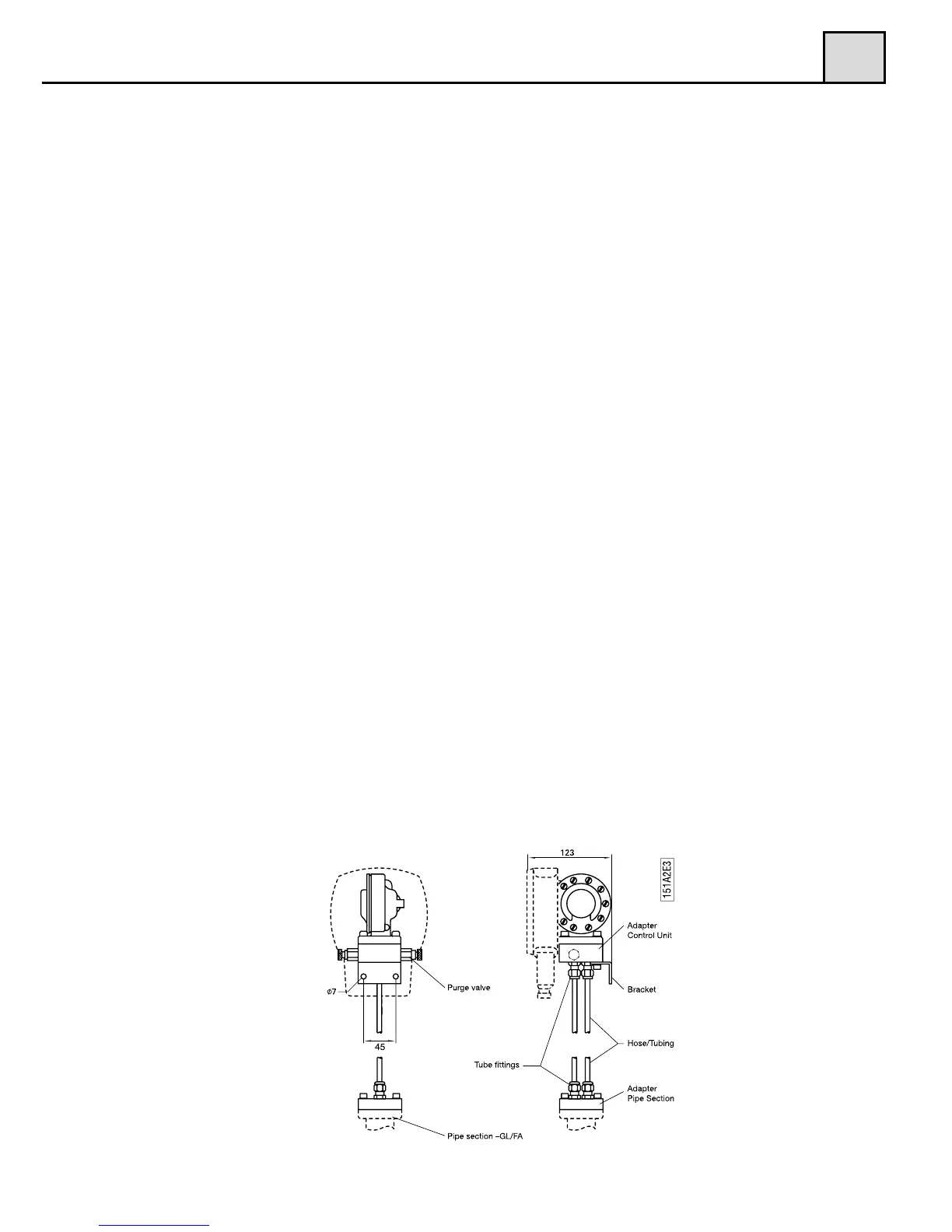
ports up to the Control Unit, it is also possible to separate the Monitor (Fig.
2) from the Pipe Section -GL/FA into two parts. The pressure is then lead
through either plastic hoses or metallic tubing depending on the liquid,
pressure and temperature.
As a standard, we supply 2x1,75 meter (5.74 feet) of PA plastic, Ø 6 mm (0,23
inch) hoses capable of handling 90ºC (194°F) and 16 bar (232 PSI), together
with two specially made adapters to be mounted on the Pipe Section and
Control Unit respectively. If your application requires metallic tubing (copper
or stainless steel) it has to be provided locally. If you are measuring a chemi-
cal liquid or gas, check with the supplier which material you should use in
your tubing. Please make sure to use only 6 mm tubing in order to suit the tube
fittings included in the delivery. There is no actual limitation in the length of
the hoses or tubing, but we recommend placing the units as close as possible
to each other, as this will help in troubleshooting and on-site calibration.
Note!!! The hoses/tubings must have the same length to avoid uneven pres-
sure. If you mount valves (not included in delivery) in the pressure hoses/tu-
bing, it will help you to easily shut them off and remove/exchange the
Control Unit at full process pressure.
The Mounting of three-way/five-way standard valve (not included in delivery)
will allow you to discharge any entrapped air/gas or condense and also provi-
de the possibility to even out the pressure between the plus and minus leg for
zero verification. Please follow the above ”Installation of the Pipe Section” af-
ter you have mounted the adapter on to the Pipe Section. As you will use ho-
ses/tubing to lead the pressure up to the Control Unit, it is possible to mount
the Pipe Section in any direction, vertically or horizontally and with the pres-
sure ports pointing up, down or to the side (pls. see section 2.3).
Separate mounting of Pipe Section and Control Unit GL/FA
Figure 2
2