23
5041A2E4
Change of Flow Direction
For GL-models, first empty the pipe system so that it is un-pressurized and
has no flow!
For FA-models, use the shut-off valves, see section 2.5
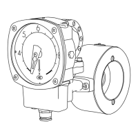
At the time of ordering, you must specify in which direction the Flow Monitor
shall be mounted i.e. from which side is the flow entering the Pipe Section and
how you would like to read the scale. (Pls. refer to fig. 6 below for alternativ-
es.) If, for some reason, the Flow Monitor is ordered with the wrong Flow di-
rection, it is possible to change this in the field. The flow direction selector
(only available in the -GL and -FA models. For -GSS and -FSS models we re-
fer to section 3.3 and 2.2) which is placed between the diaphragm housing and
the Pipe Section, determines the direction. There are two different selector al-
ternatives to choose from, the ”R” and the ”L” selector and you must use the
same selectors for all pipe section sizes. For mounting directions according to
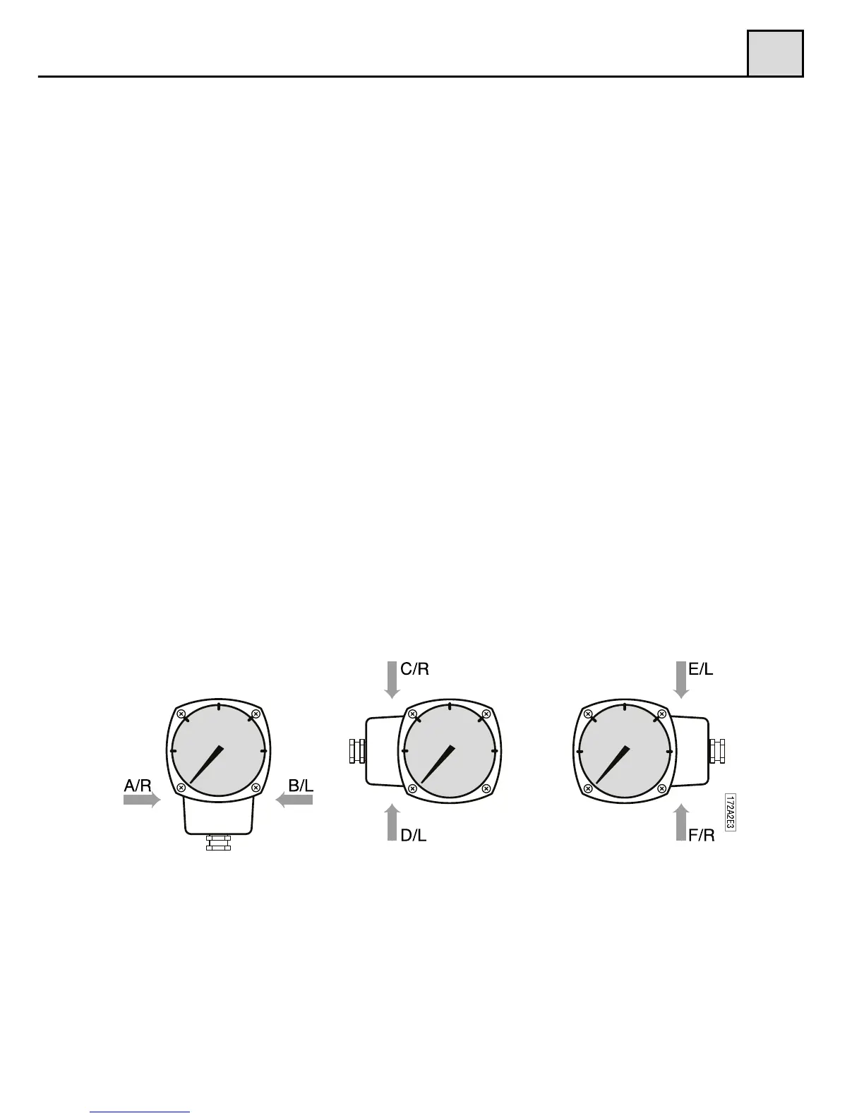
alternative A,C and F (see fig. 6), use the ”R” selector. For B, D and E alter-
natives (see fig. 6), use the ” L” selector. The flow direction selector must be
ordered as a spare part, according to the right alternative.
To change the selector, loosen the four hexagon screws, which hold the dia-
phragm housing to the Pipe Section. Remove the diaphragm housing and you
will see the flow direction selector, which is held in place by two screws.
Remove the screws and change the selector. Make sure that the four o-rings
are mounted correctly to avoid leakage. Mount the diaphragm housing to the
Pipe Section and tighten the four hexagon screws firmly.
Please also remember to turn the red arrow mounted on the Pipe Section
(-GL and -FA models), to align with the new flow direction.
3
3.4
Dial orientation and ordering code
Figure 6
3.4.2 Flow Direction Selector (until December 2012)
For GL and FA models there are two ow direction selectors to choose from,
the ”R” and the ”L” selector.
For mounting directions according to alternative A, C and F (see g. 7), use the
“R” selector. For B, D and E alternatives (see g. 7), use the “L” selector. The
ow direction selector must be ordered as a spare part, according to the right
alternative.
To change the selector, loosen the four (4) hexagon screws, which hold the
diaphragm housing to the Pipe Section. Remove the diaphragm housing and
you will see the ow direction selector, which is held in place by two screws.
Remove the screws and change the selector. Make sure that the four o-rings are
mounted correctly to avoid leakage. Mount the diaphragm housing to the Pipe
Section and tighten the four hexagon screws rmly.
Please also remember to turn the red arrow mounted on the Pipe Section
(-GL and –FA models), to align with the new ow direction.
For -GSS and -FSS models we refer to section 2.2.
Figure 7
3