21
5041A2E4
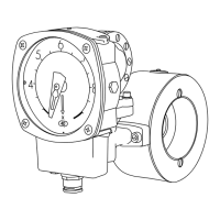
For threaded model -GL:
Untighten the bolts that hold the Pipe Section between the flanges in the pi-
ping (do not remove the threaded parts from the piping). Remove only the
number of bolts necessary to pull the Monitor from the piping, normally it ta-
kes only one bolt from the highest position, to get the Monitor out. Take out
one of the spacers that holds the orifice plate. Change the orifice plate to the
new ordered orifice plate and remember that you can install it in any direction.
Reinstall the spacer that holds the orifice in place inside the Pipe Section.
Install the Monitor in the piping system again and tighten the bolts firmly to
avoid leakage.
For threaded model –GSS:
In this model there is no loose replaceable orifice plate and therefore it is ne-
cessary to change the complete orifice section with holder, to achieve a new
flow range.
Please follow the above instructions for the –GL model for dismounting the
whole orifice plate with holder. Remove the Control Unit from the old Pipe
Section (orifice section) and install this to the new Pipe Section. Remount the
Flow Monitor into the piping system again and tighten the bolts firmly.
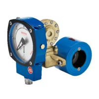
For flanged model FA-:
Follow the procedure above to loosen the pipe section from the counter flang-
es in the piping system, but note that the spacers are held in place with two
screws, which has to be untightened before removal
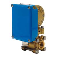
For flanged stainless steel model FSS-:
In this model there is no loose replaceable orifice plate and therefore it is ne-
cessary to change the complete Pipe Section to achieve a new flow range.
Follow the procedure above to loosen the Pipe Section from the counter flang-
es in the piping system. Remove the Control Unit from the old Pipe Section
(orifice section) and install this to the new Pipe Section. Remount the Flow
Monitor into the piping system again and tighten the bolts firmly.
Always check that no gaskets will interfere, by misaligning, with the flow
when installing the Flow Monitor.
When you change the orifice plate in order to get a new flow range, it is ne-
cessary to change the identification plate to a plate with the new range mark-
ed. This identification plate comes together with the orifice plate when you
3
21
5041A2E4
For threaded model -GL:
Untighten the bolts that hold the Pipe Section between the flanges in the pi-
ping (do not remove the threaded parts from the piping). Remove only the
number of bolts necessary to pull the Monitor from the piping, normally it ta-
kes only one bolt from the highest position, to get the Monitor out. Take out
one of the spacers that holds the orifice plate. Change the orifice plate to the
new ordered orifice plate and remember that you can install it in any direction.
Reinstall the spacer that holds the orifice in place inside the Pipe Section.
Install the Monitor in the piping system again and tighten the bolts firmly to
avoid leakage.
For threaded model –GSS:
In this model there is no loose replaceable orifice plate and therefore it is ne-
cessary to change the complete orifice section with holder, to achieve a new
flow range.
Please follow the above instructions for the –GL model for dismounting the
whole orifice plate with holder. Remove the Control Unit from the old Pipe
Section (orifice section) and install this to the new Pipe Section. Remount the
Flow Monitor into the piping system again and tighten the bolts firmly.
For flanged model FA-:
Follow the procedure above to loosen the pipe section from the counter flang-
es in the piping system, but note that the spacers are held in place with two
screws, which has to be untightened before removal
For flanged stainless steel model FSS-:
In this model there is no loose replaceable orifice plate and therefore it is ne-
cessary to change the complete Pipe Section to achieve a new flow range.
Follow the procedure above to loosen the Pipe Section from the counter flang-
es in the piping system. Remove the Control Unit from the old Pipe Section
(orifice section) and install this to the new Pipe Section. Remount the Flow
Monitor into the piping system again and tighten the bolts firmly.
Always check that no gaskets will interfere, by misaligning, with the flow
when installing the Flow Monitor.
When you change the orifice plate in order to get a new flow range, it is ne-
cessary to change the identification plate to a plate with the new range mark-
ed. This identification plate comes together with the orifice plate when you
Type plate and measuring constant
Untighten the bolts that hold the Pipe Section between the anges in the piping
(do not remove the threaded parts from the piping). Remove only the number
of bolts necessary to pull the Monitor from the piping, normally it takes only
one bolt from the highest position, to get the Monitor out. Take out the spacer
that holds the orice plate. Change the orice plate to the new ordered orice
plate and remember that you can install it in any direction. Reinstall the spacer
that holds the orice in place inside the Pipe Section. Install the Monitor in the
piping system again and tighten the bolts rmly to avoid leakage.
3
 Loading...