ET8/480, ET8/480S and ET8/480PT - TECHNICAL MANUAL - 9
7. MASTER BOARD AND FUSES
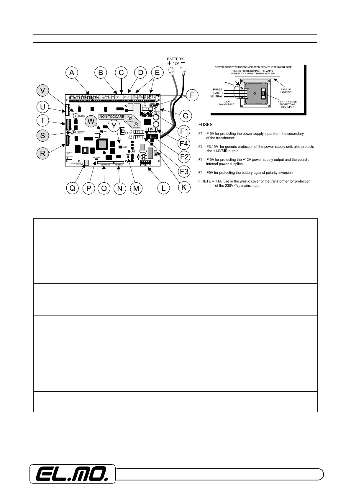
View of master board and the power supply transformer
Key:
A = Terminal board for connection of
sensor wires
B = RS485 AUX terminal board for
network connection of control units. To
use for connection with big alarm
centralization.
C = Driver terminals for transponder serial
line. The mains supply must be taken from
the terminal board alongside. If the serial
line starts from this terminal board,
connect the first 680 Ohm resistor
between A and B.
D = Driver terminals for compatible
keyboards, NADIR, AURORA and
ZENITH key points.
E = Output terminals for alarm signals,
clean contacts of the ALARM and
TAMPER relays (only for devices working
with SELV voltage), mains supply
terminals for sensors, reference for self-
powered sirens and +14V for recharging
their internal battery
F = Input terminal board of the control
unit’s TAMPER circuit for the facilitated
connection of the housing protection
microswitch.
G = Connector-type input of the voltage
originating from the secondary of the
transformer fixed to the base of the
housing.
F1 = F5A fuse protecting, see fuses table. F2 = F 3,15A fuse protecting, see fuses
table.
F3 = F 5A fuse protecting, see fuses table. F4 = T 5A fuse protecting, see fuses table. K = Connector for the connection of the
SK/SINT voice synthesis card.
L = Connection terminal board of
telephone dialler section with earth
terminal and line sectioning. Connect only
to TNV circuit.
M = Variation bond of the sensitivity to the
entering ring. Normally, the bond is closed
for standard sensitivity, open to reduce
the sensitivity.
N = Connector for future uses.
O = Connector for connection of printer
with Centronics parallel interface. Use, for
example, a CP8PRINT printer.
P = Connection bond of the NIMH battery
for the clock. Close only after installation.
Q = MINIDIN connector for the
programming in direct link-up with PC and
WINASSIST or specific BROWSER, for
the up-dating of the control unit release or
for connections with CEI 79-5/-6 protocol.
Use the CP8/SER2 cable.
R = Connector for I6 or I7 reader.
S = Contrast adjustment of display.
V = Warning buzzer.
Items not available in ET8/480S control
unit.
T = Signals 1 and 2 connectors for
connection of CP8/REL and UNIREL
boards for MFT output function.
U = Connector for the connection of the
MP64/DRTP driver board for the
ET848/SIN mimic repeater.
W = SPEC push-button for special reset
operations to be used solely with ET8/48S
control unit.
Y = RESET push-button for resetting the
control unit or returning to factory status,
DEFAULT. These operations are
described in the pertinent section.