33
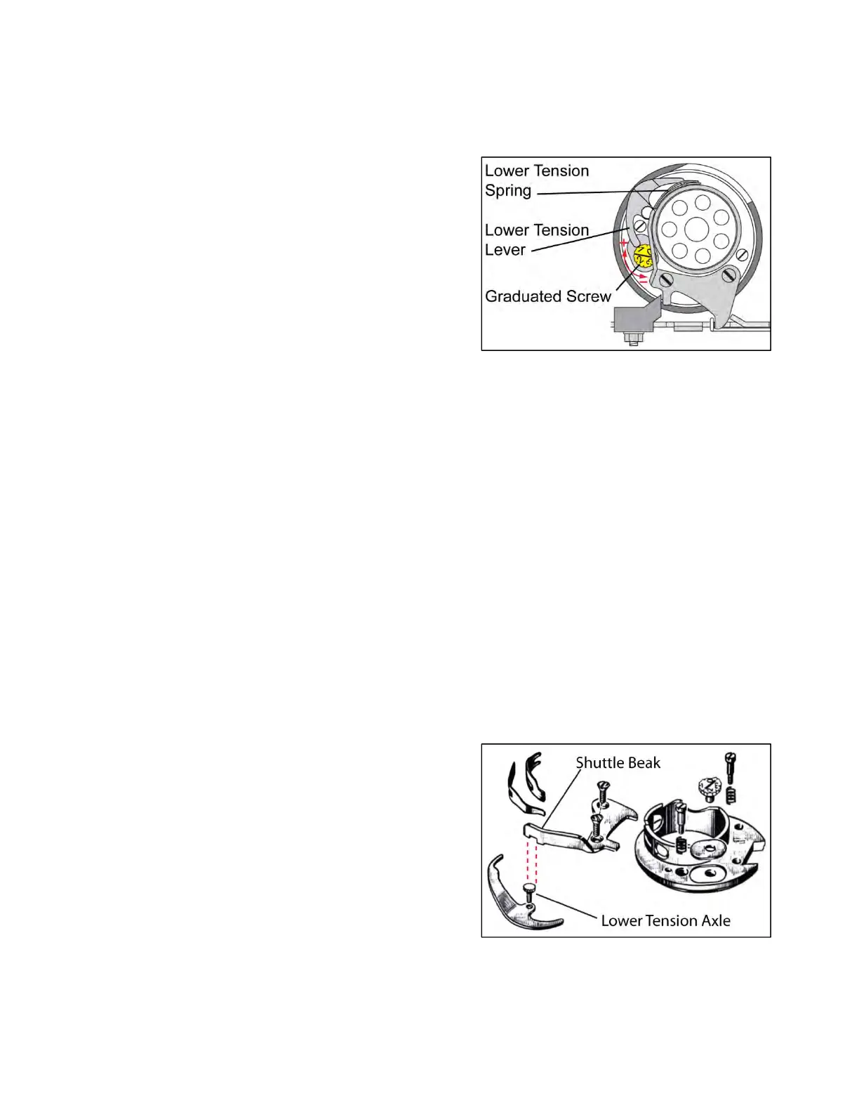
LowerTensionDevice
Howitworks
TheGraduatedScrewadjuststhelowerthreadtensionby
pivotingtheLowerTensionLever,therebychangingtheforce
appliedontheLowerTensionSpring.
TurningthescrewClockwiseincreasesthetension.
TurningthescrewCounterclockwisedecreasesthetension.
TherearedetentsaroundtheperimeteroftheGraduated
Screwheadat¼incrementsbetween0and3.5.
Normaltensionshouldbesetat“1”asshown.
Revisions
Therewerenumerouschangesmadetotheshuttleassemblyincludingthe:Upperguardring,Shuttlebeak,
Graduatedscrew,Spacingplate,Upperguardringscrewsandspring.Pleaserefertothe3revisionsoftheparts
catalogstoidentifywhichconfigurationappliestothemachineyouareservicing.Changesarenotedwiththe
machineserialnumberwhenthechangewasmade.
Theindividualcomponentsonthemachineyouareservicingmayappeartobedifferentthanthoseillustrated
here.However,itdoesnotappearthatanyofthechangesaffecthowthelowertensionisadjustedinthis
section.
Checkingthenormaltension
Withthegraduatedscrewsetat"1,”aslighttensionmustbefeltwhenafinethread(No.120)isdrawnbyband
betweenupperguardringandlowertensionskid.Forthistestthebobbinthreadmustbeloosesothatitdoes
notpullandturnthebobbin.
Ifnotensionatall,oriftoomuchtensionofthelowerthreadisobserved,adjustasfollows:
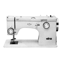
Adjustingthenormaltension
RemovetheUpperGuardRingfromtheshuttle.
LoosenbothShuttleBeakfasteningscrewsabout2turns,and
thenlifttheportionoftheshuttlebeakwiththenotchwhich
lockstheLowerTensionAxle,preventingitfromturning.
TurntheLowerTensionAxletoadjustthenormaltension
setting.Toincreasethetension,turnitclockwise;todecrease
tension,turnitcounterclockwise.
Tightenbothshuttlebeakfasteningscrewsandconfirmthat
thelowertensionaxleisproperlylockedbytheShuttleBeak.
Replaceupperguardringandtightenthetwoscrews.Makesurethatthetwosmallsprings(undertheheadsof
theabovescrews)arealsoinserted.
Recheckthetensionoflowerthreadasexplainedabove.Ifnecessary,repeataboveadjustment.