EasyManuals Logo

Elster 6 Series Wiring Instructions

Elster 6 Series
31 pages
To Next Page IconTo Next Page
To Previous Page IconTo Previous Page
Page #19 background imageLoading...
Page #19 background image
5
Communication Connections
UFM Series 6
Wiring Instructions
Page 19 of 31
* It is also possible to ‘link’ the second frequency to the first, then it has the same output,
only 90° phase shifted.
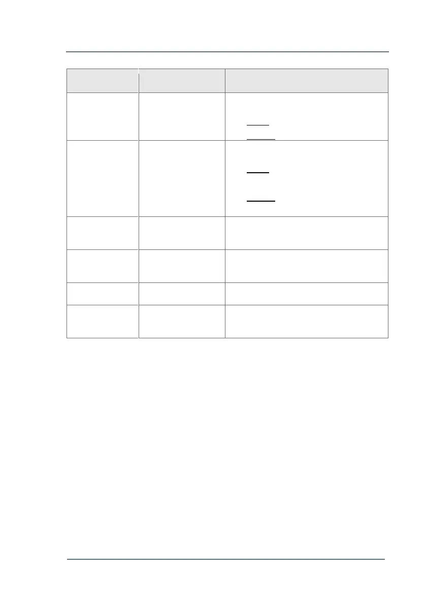
Table 7: Standard factory settings of communication connector TB3
Factory settings can be changed by using the software package
SonicExplorer. Communication between the meter and SonicExplorer can
only be made through a network connection. Please see Chapter 5.1 -
Network (TB2 and J4) (p.14).
Pin Number
Signal name
Description
13 - 14
Digital output 2
Flow direction
Open: Flow direction positive
Closed: Flow direction negative
11 - 12
Digital output 1
Partial Failure
Open: Performance of at least
one path is below 10%
Closed: Performance of all paths
are above 10%
9 - 10
Frequency output
2*
Q-line Reverse flow, 0 3000 Hz
7 - 8
Frequency output
1
Q-line Positive flow, 0 3000 Hz
4 - 6
Serial comm. 2
RS 485, U_DATA, Baudrate 4800
1 - 3
Serial comm. 1
RS 485, ModBus RTU, Baudrate
9600

Other manuals for Elster 6 Series

Questions and Answers:

Question and Answer IconNeed help?

Do you have a question about the Elster 6 Series and is the answer not in the manual?

Elster 6 Series Specifications

General IconGeneral
BrandElster
Model6 Series
CategoryMeasuring Instruments
LanguageEnglish

Related product manuals