Operating & Maintenance Instructions 19
_____________________________________________________________________________________
14 PULSING OUTPUT
14.1 Output Configurations
An opto-isolated pulsing output can be provided as an option. The output is available via the
meter auxiliary terminals in the following configurations:
Single rate meter - The output is connected to the meter's two auxiliary terminals and is
fully isolated.
Two rate meter - This output is referenced to neutral and brought out to one auxiliary
terminal. The output is non-isolated.
14.2 Output Characteristics
When the meter is in anti-creep mode the output is not active.
The pulse/kWh and pulse width is configured as indicated below.
Pulse width – nominal (ms) 10, 20, 30, 40, 50, 60, 80, 100, 120, 160, 200, 250 or equal mark-space (1)
Pulses/kWh 10 20 25 40 50 100 200 250 500 1000
Wh/pulse (2) 100 50 40 25 20 10 5 4 2 1
Maximum voltage (Umax) 27V d.c.
Maximum current in On-state 27 mA
Minimum current in On-state 10 mA
Maximum current in Off-state 2 mA
1), (2) see below re: representation of consumption.
Note: Care should be taken in selecting the combination of pulse width and pulses /kWh.
Avoid combinations that may give insufficient spacing between pulses at maximum load.
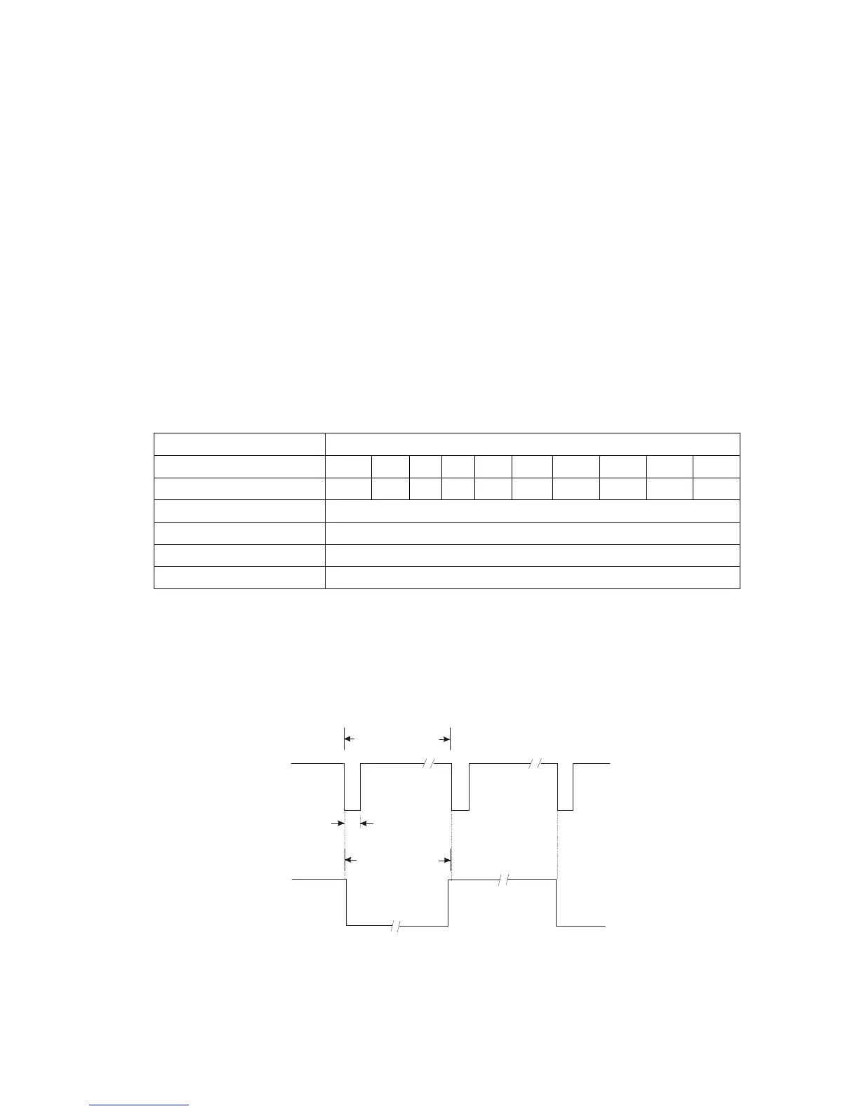
Pulsing Output
High Impedance
Low Impedance
High Impedance
Low Impedance
Energy = Pulse
consumed (2) value
Energy = Pulse
consumed (2) value
Set to equal Mark-Space
Pulse width (1)
Note: When configured for equal mark-space, each transition indicates the consumption
of the specified energy value.
The Pulse output meets the requirements of IEC 62053-31.