Eltek Energy AS
Tel. +47 32 20 32 00
Internet: www.eltekenergy.com E-Mail: eltek@eltekenergy.com
Form 174-gb-v1-C01_356808-103_qstart-inst-comm-oper_minipack-pss.doc_mfm_2006-12-29
INSTALLATION CHECK LIST
System Data
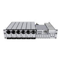
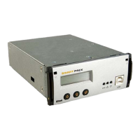
Minipack PS System
Minipack Power Supply System, type: Article No.:
Site, name:
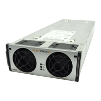
Serial No.: Software, version No.: Rectifiers, type & number of:
AC Input Voltage, measured: Battery Type: Battery Capacity: Installation carried out by, name:
Site Preparations
CARRY OUT FOLLOWING
:
OK
1. Organize the installation site
o Prepare a 2U high spare location in existing 19”, 250 mm cabinet; Check min. clearance: front access, 60 cm
o Ensure the installation site is suitably ventilated and in a non-explosive atmosphere.
2. Prepare the installation tools
o Check that insulated tools suitable for telecom installations are used
3. Prepare AC Supply: AC input cable(s) and fuses
o Check the AC supply is the correct type, and that the external AC fuses and AC input cable(s) are suitably rated
Mechanical Installation
Power is OFF!
CARRY OUT FOLLOWING
:
OK
4. Remove packaging and check equipment
o Check you have received all the parts and correct documentation.
o Inspect the equipment for physical damage (report any damages)
o Leave rectifier modules in their packaging or in the selves, if factory installed. (commissioning task)
5. Remove the cabinet’s top cover and dummy front panels
o Check that cable entry from the top is possible
o Connection terminals are accesses by opening the drawer shelf
6. Position and fasten the subassembly
o Subassemblies in existing 19” or in ETSI cabinets, using brackets.
7. Mount the external batteries on the shelves
o Start (if applicable) on the lower shelf first, and continue upwards
o Do not terminate the battery cables yet!
8. Open the Minipack drawer shelf and lift the plastic cover
o Unlock the upper and lower screws and slide the drawer shelf open, then lift the Melenex plastic cover
Electrical Installation
Power is OFF!
CARRY OUT FOLLOWING
:
OK
9. Make the system completely voltage free
o Switch OFF or remove all load fuses (MCB1, MCBx), battery fuses (Fb1, Fbx) and external AC supply fuses
10. AC Connections
o Check AC configuration: Make available 3 single phase mains feed and earth (PE)
o Connect the AC Earth wire (PE) to the terminals AC Earth (PE)
o Connect the AC input cable(s) to the terminals. Cable and terminal block labeling are to correspond
11. DC Connections ⎯ Load Circuits
o Terminate DC Earth (TE):
Common DC Output Rail is connected to TE at only one place
o For each DC load, connect one of the cables to the common DC output terminal; the other to the fuse terminal
12. DC Connections ⎯ Alarm & Signal Circuits
o Refer to your system’s connection drawings and configuration, or to the Quick Start Guide
o Terminate Alarm Circuit cables to the relay output terminals
o Terminate Signal Circuit cables to the digital input/output terminals
13. DC Connections ⎯ Battery Cables Careful! Use correct polarity.
For each battery shelf,
o Mount 3 intercell links to connect in series 4 battery blocks
o Connect battery cables to fuses and Common Battery, and to the shelf’s outer terminals; black (+); blue (-)
o Connect battery symmetry cables, if applicable, to the input terminals
o Connect the temperature sensor cable, if applicable, to the D-Sub plug or input terminal, and fix the sensor (at the
end of the cable) to a suitable place in the middle of the installed battery bank
Approval
Responsible of installation, sign.: Date: Approved by customer, sign.:
EMC
regard
Electric
shock
Device
hazard
Electric
shock