Quick Start Guide Minipack PS System
356808.103, v1-2006-12
17
Standard Alarm Relays & Digital Inputs
Connections
The alarm outputs in Minipack systems use the Fail-Safe
Operation Mode (relay coils energized in the system’s
normal operation mode). When the system is in alarm
mode, the alarm relay coils are de-energized.
In order to implement monitored fail-safe digital inputs
circuits, the external relay coil must be energized and the
contact closed in the system’s normal mode of operation.
See the figures.
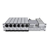
Alarm Interface Card ~ Terminals & Pin-out
The Smartpack controller’s alarm and digital input monitoring signals are accessible from the
controller’s rear panel, on mini power connector CON1 (2 outputs & 2 inputs).
Using the Alarm Interface Card (Art. 218470) plugged to Smartpack’s CON1, you can make
the signals on CON1 accessible on terminal block X1.
For detailed information about the card’s pin-out location and terminal block connections, see
the figures in this section.
Standard Relays & Digital Inputs
Correct Use of Digital Inputs (example)
Normal Mode
External Relay Y
(Energized coil)
+
—
Digital Input