Quick Start Guide Minipack PS System
356808.103, v1-2006-12
8
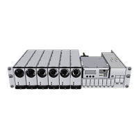
Location of Components, GA drawing
Refer to the specific drawings included with your Minipack PS system, for
information regarding the exact location of components in your system.
Installation
NOTE: For information about connecting
Battery Symmetry, Temperature Sensor,
Alarm and Monitoring circuits, refer to
section “Miscellaneous”, and read the
Battery Monitoring, Alarms & Monitoring
chapters.
CAN1
CAN bus communication with rectifiers (to Smartpack rear)
CON5A, For internal connections
(to Smartpack rear)
Common Battery (+)
X7A, Battery connections
DC Earth
X7A, Exchange Ground (EG) or system
ground. Link connected to chassis
Fb1, Fb2
Battery connections (−)
AC Mains
AC Mains & Earth (PE) Terminals
Plastic Protective Cover fo
ack rectifiers
CAN1
CAN bus communication with rectifiers
(to Smartpack rear)
CON5A, For internal connections
(to Smartpack rear)
Common Battery (+)
X7A, Battery connections
DC Earth
X7A, Exchange Ground (EG) or
system ground.
Link connected to chassis
Fb1, Fb2, Fb3, Fb4
Battery connections (−)
AC Mains
AC Mains & Earth (PE) Terminals
Plastic Protective Cover fo