section of this folder. Also, refer to the system’s specific drawings.
Installation
For external AC fuses and AC input cable ratings, refer to your site’s AC
supply specification. In general, a site with better AC supply quality
(stable nominal voltage) may use smaller breakers.
Mechanical Installation
Power is OFF!
Carry out the following:
4 Remove packaging and check equipment
o Check you have received all the parts and correct documentation
o Inspect the equipment for physical damage (report any damages)
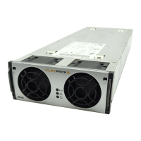
o Leave rectifier modules in their packaging or in the selves, if
factory installed. To be installed under commissioning
5 Remove the cabinet’s top cover and dummy front panel
o Connection terminals are accesses by opening the drawer shelf
o Battery shelves (if any) are placed behind the lower panels
6 Position and fasten the subassembly
o Minipack is fastened in existing 19” or in ETSI cabinets, using
brackets
7 Mount the external batteries on the shelves
o Start (if applicable) placing the batteries on the lower shelf first,
and continue upwards
o Do not terminate the battery cables yet!
8 Open the Minipack drawer shelf and lift the plastic cover
o Unlock the upper and lower screws and slide the drawer shelf
open; read the Installation & Maintenance Details chapter
o Lift the Melenex plastic cover to access the connection terminals
Electric
shock
Device
hazard
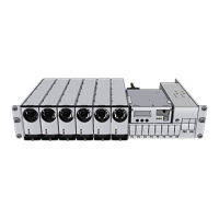
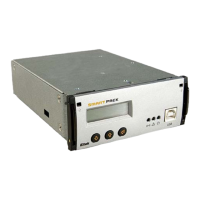
Minipack PSS, Doc. Chart, Spec.
Drawings, CD-ROM
Minipack drawer shelf slid out in
the maintenance position
Plastic Cove
Preparing the Installation Site
Begin preparing the following:
1 Organize the installation site
o A 2U high spare location in existing 19”, 250 mm cabinet
o Min. Clearances: 60 cm in front
o Explosive atmospheres are to be avoided. Ensure suitable
ventilation
2 Prepare the installation tools
o Use insulated tools suitable for telecom installations
3 Prepare AC Supply: AC input cable(s) and fuses
o Correct type AC supply is available
o External AC fuses have correct rating
o AC input cable(s) are sized correctly
EMC
regard
600 mm
2U
200 mm