Rev.Draw. No.Page
Format
Block Diagram Minipack 48Vdc
3,2kW
Consultant
Replace for Replaced by
Copyright A/S Eltek. All rights reserved
Eltek
2023227
Sym. Date/SignAlteration
A3
ProjectionScale
Approved
FRNONO
Draw
ORSKNO
Design
ORSKNO
Date
22 Dec. 2006
1a1 of 1
--
-
Y X
LVBD
-FB1
-FBn
Battery Strings
Circuits -48Vdc
0V
Customer
connections
Customer
connections
Load circuits -48Vdc
DC Earth (TE)
Customer connections
1: Optional 9 pin D-sub RS232 connection.
Can be mounted in front or on rear side of
Smartpack. Replaces ”Ext. Battery Connections”
when mounted on the rear side of Smartpack
2: Optional Web/SNMP (ENET) connection.
Replaces ”Ext. Alarm I/O Connections”
Customer
connections
CON5
System Connections
CON4
Battery connections
CON2
Ext. Alarm I/O Connections
2: Optional: Web/SNMP (ENET)
CON1
Alarm I/O Connections
USB 2.0 type B port
(PC connection)
9
1: Optional: RS232
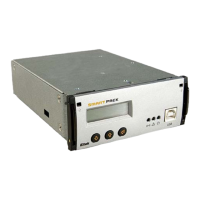
Smartpack
monitoring and
control unit
10
CAN port
15
15
9/15
CON3
Ext. Battery connections
1: Optional: RS 232
8/26
CAN port
USB
Rear connections Front connections
8
8
See Std. Documentation
356804.10x
See Std. Documentation
356804.10x
NA for Smartpack Web/SNMP
NA for Smartpack RS232 rear
1
2
3
4
5
6
7
8
9
10
*X3
Battery Connections
Con 3A*
Battery Connections
Battery Connections
200576
15
SERIAL
DIFF
S1
+
-
Batt. Symmetry 5
+
-
Batt. Symmetry 6
+
-
Batt. Symmetry 7
+
-
Batt. Symmetry 8
+
-
Temperature Sense 2
12
13
14
+
-
+
-
11
Battery Current 2
Battery Fuse Fail 2
15
*Con 7
Temp sense
1
2
3
4
5
6
7
8
9
10
*X4
Battery Connections
Con 4A*
Battery Connections
Battery Connections
200576
15
SERIAL
DIFF
S1
+
-
Batt. Symmetry 1
+
-
Batt. Symmetry 2
+
-
Batt. Symmetry 3
+
-
Batt. Symmetry 4
+
-
Temperature Sense 1
12
13
14
+
-
+
-
11
Not Connected
Not Connected
15
*Con 6
Temp sense
COM
NO
NC
1
Alarm Outputs and
Digital Inputs
218470
10
2
3
4
5
6
7
8
9
10
+
-
+
-
Digital Input 1
Digital Input 2
Relay 1
COM
NO
NC
Relay 2
Con 1A*
Alarm I/O
Connections
X1*
Alarm I/O Connections
Alarm Outputs and
Digital Inputs
218473
26
1
2
3
4
5
6
7
8
9
10
11
12
13
14
15
16
17
18
19
20
+
-
Digital Input 3
+
-
Digital Input 4
+
-
Digital Input 5
+
-
Digital Input 6
COM
NO
NC
Relay 3
COM
NO
NC
Relay 4
COM
NO
NC
Relay 5
COM
NO
NC
Relay 6
Con 2A*
Ext. Alarm I/O
Connections
X2A*
Ext. Alarm I/O Connections
X2B*
Ext. Alarm I/O Connections
Customer
connections
Mains input
terminals
* To be labeled
8
pin 1-8
8
7
6
5
4
3
2
1
L1
N
L2
N
L3
N
PE
PE
213333
Underwiring MPBB 6pos 3AC
X5*
Power
output + Y7
Power
output – Y8
Power module 1
PE
N
L
+
-
Power module 2
PE
N
L
+
-
Power module 3
PE
N
L
+
-
Power module 4
PE
N
L
+
-
CAN1
Smartpack
Power -/CAN bus
Interconnections
217915
Dist board 1 Minipack System MCB
10 pos load
4 pos batt
Con5A*
Smartpack Connection
213213
JP1 JP2
NEG. DIST.
POS. DIST.
NEG. DIST.
POS. DIST.
15
1
2
3
4
Batt. Fuse Fail +
Batt. Fuse Fail -
LVD 1A
LVD Common
TB1
System connections
3
4
5
6
X6A*
DC output +
7
8
9
10
SH1
Y1 Power input +
Y2 Power input -
Y7
Y6
Y5
Y4
Y3
Y9
To battery contactor
To Dist
board 2
Optional
Y X
LVLD
K1
Y12
Y18
Y19
Y20
X7A*
To battery +
1
2
215792
Dist.Board 2 MPBB 100A
10pos G1
X6B*
DC output -
Y5 low pri load
Y4
Y3 Fuse
alarm
Y2 high
pri load
Y1
F1
F2
F3
F4
F5
F6
F7
F8
F9
F10
Y6
Y7
Y24
Y25
10
9
8
7
6
5
4
3
2
1