Quick Start Guide Minipack PS System
356808.103, v1-2006-12
12
Front Keys and display, menus, etc.
Operation
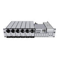
Minipack Rectifier Module — front panel
Power LED is OFF (mains unavailable), Flashing
(controller accessing information) or ON (powered).
Warning LED is ON (derating or similar minor
warning), Flashing (over-voltage mode) or OFF (OK)
Alarm LED is ON (shutdown or similar major alarm)
or OFF (OK, no alarm)
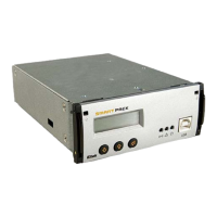
Smartpack Control Unit — front keys, display, etc
Display: is in Status Mode (displays the system’s
status) or in Menu Mode (displays the menu structure).
Operation: Press on the
key to change from
Status Mode to Menu Mode. Press the
or
keys to scroll up or down and navigate to find menu
options (function or parameter). Press then the
key to select the function.
Menus: When you “enter” Menu Mode (Level 1), you
access the User Options. You may also scroll down to
password protected Service Options. Default password
<0003> should be changed.
Powe
larm
LED Lamp (red)
Software Menus ~ Smartpack controller
User menu <UserOption>
AlarmResetÆ
NomVolt
BoostVolt
LoBattMaj
VoltageInfo LoBattMin
HiBattMaj
HiBattMin
LVBD
LVLD 1.1
DisplayMessagesÆ
Message ↓↑
SoftwareInfoÆ
SerialNumberÆ
NoOfRects. nn
RectCurrent
Rectifier Info RectSerialNumber
Rect.PrimaryVolt
Rectifier Status
Rectifier Temp
Rect. OutputVolt
Rectifier SW Ver
NoOfPhases nn
Mains Info Mains Status
Mains Voltage
Temp Level InfoÆ
Level ↓↑
NoOfString Nn
BattStringCurr ↓↑
Battery Info
BattStringTemp ↓↑
BattBlockVolt ↓↑
Level 2 Level 3
…
Firmware 402073.003 1v00
Service menu <ServiceOption>
NomVolt ↓↑
BoostVolt ↓↑
LoBattMa