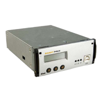
2 The Smartpack Controller
User’s Guide Smartpack Monitoring & Ctrl Unit,
350003.013, v5-2006-11
11
Software Assignment ⎯ Rectifiers
Each rectifier in the Smartpack-based DC power system is automatically configured by
the Smartpack controller with a unique CAN bus ID number (software-assignment).
When the rectifiers are hot-plugged in the power shelves the first time, the Smartpack
controller dynamically assigns the rectifiers with the next available ID number (software-
assignment), and automatically increases the number of communicating rectifiers on the
CAN bus. Also, the controller registers the rectifiers’ ID numbers, or CAN bus address
(01, 02…), together with their serial numbers.
When a previously installed rectifier is hot-plugged in the power shelf again, it retains its
previous ID and serial number, unless reassigned during a Reset Rectifier command.
CAN bus Termination
To ensure a correct bus communication and avoid data reflection, you must always
terminate the CAN bus with two 120Ω resistors at both ends of the line (60
Ω
bus
impedance), see Figure 8. The CAN bus is connected using CAT5 twisted-pair cables.
Figure 8 CAN bus terminated with a 120Ω resistor on both line ends (60Ω bus impedance)
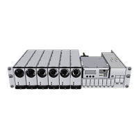
The example in Figure 9 shows a Flatpack2 DC power system expanded with a slave
controller to implement additional digital inputs, relay outputs or similar functionality.
Figure 9 A Flatpack2 DC power system expanded with two controllers
120Ω
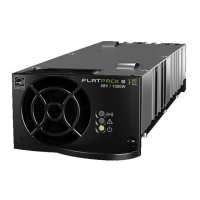
Flatpack
k assigns ID numbers to the recti-
fiers (software-assigned). The Smartpack’s
ID numbers are assigned by DIP switches
on the controller’s side.
120