2 The Smartpack Controller
6 User’s Guide Smartpack Monitoring & Ctrl Unit,
350003.013, v5-2006-11
2. The Smartpack Controller
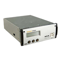
The Smartpack controller is a monitoring and control unit used as the vital nerve center
of the DC power plant. You operate the system from the elegant front panel, using three
front keys and the LCD-display. They represent the main interface between you and the
system.
You can also operate the system locally via a PC using Eltek’s PowerSuite application, or
remotely via modem, Ethernet and the Web. The module then utilizes the USB- or RS-
232 ports to interface with a local PC, SNMP or Web adapters. See also chapter
“Technical Specifications”, on page 21.
Key Features
Front panel LCD and buttons for on-site service without PC.
USB- or RS-232 interface for PC connection locally or remote monitoring
and control via modem, Ethernet, web or SNMP.
Main program upgrade via USB port and the FWLoader application
6 user programmable relay outputs for traditional remote control
6 user programmable inputs for monitoring of other equipment on site
Battery monitoring and testing without site attendance
Temperature compensated charging for increased battery lifetime
Battery lifetime indication
Password protected operator access levels
Alarm/event log with time and date
Windows-based PC communication software
Block Diagram
Figure 2 Block diagram of the Smartpack Battery Extended controller showing the module’s
main functions
Smartpack Controller
Microprocessor
FLASH & EEPROM Memory
256Kb
EEPROM
512Kb
CAN1
Power Bus
The microprocessor is the heart o
the system and represents the
intelligence in Smartpack controller.
The main program and dynamic
data are stored in Flash memory
chips, easily upgraded via the USB
or CAN ports
CA
port (2)
for communication with rectifiers and
other controllers on the CAN bus
DIP switches fo
configuring the controller’s
CAN bus ID numbe
24 / 48 / 60VDC Input supply
Power supply
with regulated supply voltages
for internal and external use
(plug-in PCB)
ll customer-specified functions,
calibration and log data are stored in
EEPROM chips
DIP switch
Power supply
Flyback rectifier
Step Down
Reg.+5V
Step Down
Reg. ±12V
CON5
System Connections (internal)
Inputs signals
(measurements)
for system reference(1),
battery current, battery &
load fuse fail (3)
Output signals (control)
for LVD latching relays (2)
CON4
Battery Connections
(internal)
Inputs signals
(measurements) for battery
symmetry (4), temperature
sense (1)
CON1
Alarm I/O Connections (customer)
Inputs signals
(measurements) for con-
figurable digital inputs (2)
Output signals (control)
for Alarm relays (2)
CON3
Battery Connections (internal)
Inputs signals
(measurements) for battery
symmetry (4), temperature
sense (1), battery current
(1), battery fuse fail (1)
CON2
Alarm I/O Connections (customer)
Output signals (control)
for Alarm relays (4)
Inputs signals
(measurements) for con-
figurable digital inputs (4)
USB
Serial Bus
USB 2.0 type B port (1)
serial communication interface with
PCs and computer devices