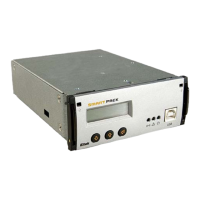
2 The Smartpack Controller
10 User’s Guide Smartpack Monitoring & Ctrl Unit,
350003.013, v5-2006-11
CAN Port Signals ⎯ Internal Connections
CAN port 1 and 2 are electrically identical, and
are used to enable connection of the CAN bus
incoming and outgoing CAT5 cables.
A special RJ45 plug with built-in 120Ω end-of-
line resistor can be connected to one of the
CAN ports; refer to Figure 8, page 11.
CAN ports’ pin 1&2 may supply the slave
controller with 12VDC, 16W via the CAN bus.
Figur 7 CAN port signals
CAN bus
The Smartpack-based DC power systems utilize the CAN
1
bus ⎯ a digital interface
architecture that supports a dedicated communication channel between the controllers
and each of the rectifiers.
CAN bus Addressing
Eltek’s CAN bus may address a maximum of 60 nodes. Among them, you may connect a
maximum of 8 Smartpack controllers and or 50 rectifiers.
Hardware Assignment ⎯ Controllers
The Smartpack controller is factory configured with a
unique CAN bus ID number, using DIP switches on the
side of controller (hardware-assignment). See Figure
3, page 7.
In a distributed DC power system with several
Smartpack controllers, the master is configured with
ID # <1>, the slave with ID # <2> and so on. Refer
to the table in this chapter and Figure 9, page 11.
When a new Smartpack controller is inserted in an existing system, the controller will
recalculate the number of connected rectifiers, reassigning them with the same ID
numbers as they already have in memory. Read “Software Assignment”, page 11.
1
Control Area Network. Serial protocol utilised for communication between Eltek’s
rectifiers and controllers
CAN Bus Connections
Smartpack
controller
CAN port 2
RJ45