2 The Smartpack Controller
User’s Guide Smartpack Monitoring & Ctrl Unit,
350003.013, v5-2006-11
7
Typical Applications
The Smartpack controller employs CAN bus communication with the rectifiers in the
Smartpack-based DC power system ⎯ and other bus-connected Smartpack controllers in
the system ⎯ thus enabling flexible expansion of system functionality and number of
measuring points. System components can be set up and upgraded to meet the demand
of any tailor-made power solution.
Location of Connectors & Communication Ports
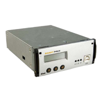
You can easily connect the Smartpack
controller to a PC, plugging a standard USB
A-B cable to the USB port on the front of the
controller and to any available USB port on
the computer.
The Smartpack controller is configured from
factory ⎯ via DIP switches on the side ⎯ with
an ID number for CAN bus communication.
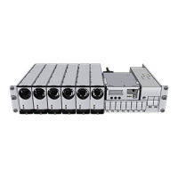
On the controller’s rear panel ⎯see Figure 4
⎯ you find two identical RJ45 CAN ports (for
incoming and outgoing CAT5 twisted-pair
cables) to connect the controller to the CAN
bus. See also chapter “CAN bus”, on page 10.
Figure 3 Front access USB port, and DIP switches for ID configuration on the side.
The Smartpack controller’s system cable connections are located on the controller’s rear
panel. These connections are used for monitoring and controlling the system, the
batteries, alarm relays and status of external equipment.
Figure 4 Rear plug connections on a Smartpack Battery Extended controller
USB 2.0 type B port
(PC connection)
DIP switches
(CAN ID number)
Extended
D-sub, 15 pins, male (Internal)
Battery Connections
D-sub, 15 pins, male (Internal)
System Connections
D-sub, 15 pins, female (Internal)