Do you have a question about the Embention Veronte and is the answer not in the manual?
Provides a diagram and overview of the Veronte Flight Control System components.
Details the Veronte Air component for real-time guidance, navigation, and control.
Explains the Veronte Vision variant with added video/vision capabilities.
Describes the Veronte Ground component for manual control and range extension.
Outlines Veronte Pipe software for ground segment mission management.
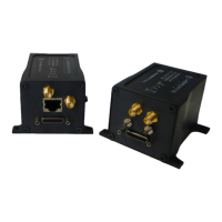
Details the anodized aluminium enclosure with EMI shielding and IP protection.
Provides dimensions and recommendations for mechanical mounting of the unit.
Discusses methods for vibration isolation to improve performance and lifespan.
Explains considerations for selecting the optimal placement on the aircraft.
Covers configuring the unit's orientation relative to aircraft body axes.
Identifies and describes the purpose of each connector on the Veronte unit.
Specifies compatible mating connectors for various Veronte ports.
Offers advice for optimal antenna placement to ensure best performance.
Details the static and pitot pressure input lines and their installation.
Explains power input requirements, voltage range, and battery compatibility.
Details the pinout and functionality of the 25-pin Micro-D I/O connector.
Describes the specific I/O signals for the Veronte Vision model.
Details the I/O signals available on the Veronte Expander module.
Explains how to connect and configure a joystick for manual flight control.
Covers the RS-232 connection for integrating an external radio system.
Details the individual wire leads for the ruggedized IP67 version.
Summarizes key performance parameters including weight, temperature, and datalink.
Provides a solution for reducing noise on the GND connection to improve GPS signal.
Details the wire colour code for the 25-pin Micro-D connector.
Illustrates a typical connection example for a multicopter setup.
Illustrates a typical connection example for a fixed-wing aircraft.
Illustrates a typical connection example for a helicopter setup.
| Manufacturer | Embention |
|---|---|
| Category | Autopilot System |
| GPS | Yes |
| IMU | Yes |
| Barometer | Yes |
| Operating Temperature | -40ºC to +85ºC |
| Supported Platforms | Fixed-wing, VTOL |
| Autopilot Modes | Manual, Stabilized |