2.1.6. Connector Layout
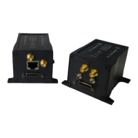
Figure 7: Veronte Connectors
RF antenna (SMA Jack Female)
GPS antenna (SMA Jack Female)
Veronte power and I/O (Micro-D)
Static pressure port (Fitting 5/64in)
Dynamic pressure port (Fitting 5/64in)
Expansion board (Micro-D)
Composite Video (SMA Jack Female)
Table 1: Veronte connection panel
For both pressure ports, mating with clamped 2mm internal diameter flexible tubing is
recommended.
2.1.7. Mating Connectors
RF antenna
(SMA Jack Female)
SMA Plug female, low-loss cable is recommended (e.g. RG-174, RG-316)
Antenna 900 MHz Whip, 1/2 wave Omni directional 2 dBi
GPS antenna
(SMA Jack Female)
SMA Plug female, low loss cable is recommended (e.g. RG-174, RG-316)
Active Antenna GPS: Gain min 15dB (to compensate signal loss in RF Cable)
max 50dB, maximum noise figure 1.5dB, power supply 3.3V max current 20 mA
RJ-45 Plug Shield, Cat 5e
Receptacle 25-pin Micro-D connector
Molex: 83424-9019(18in, 28AWG) Commercial Version
Norcomp: CCA-025-I18R152 (18in, 28AWG) Commercial Version
ITT Cannon: MDM-25SH003L (18in, 26AWG) High performance version
Table 2: Mating Connector Table
2.1.8. Antenna Integration
The system usesthree antennas to operate that must be installed on the airframe, one for
radio communications and another for GPS positioning. Here you can find some advices for
obtaining the best performance and for avoiding antenna interferences.