2.1.3. Vibration Isolation
Although Veronte ultimately rejects noise and high-frequency modes of vibration with
electronic filters, an adequate vibration isolation design can improve the performances and
extend the lifetime of Veronte.
Veronte can be mounted in different ways in order to reject the airframe vibration. The
simplest could be achieved by just using a double-sided foam tape on the bottom side of
Veronte. Other ways may use some external structure which could be rigidly attached to the
airframe and softly attached to Veronte (e.g. foam, silent blocks, etc.)
The user should take into account that wiring should be loose enough so vibrations may not
find another way to enter the aircraft system.
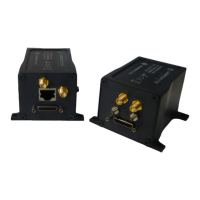
In cases where Veronte isolation is not viable, it is
possible to use soft engine mounts. It is also
recommended when there are other sensible payloads
like video cameras or for high vibration engines.
2.1.4. Location
The location of Veronte has no restrictions. You only need to configureits relative position
with respect to the centre of mass of the aircraft and the GPS antenna. The configuration of
the location of Veronte can be easily configured usingVeronte Pipe Software.
2.1.5. Orientation
The orientation of Veronte has no restrictions either. You only need to configure Veronte
axes with respect to the aircraft body axes by means of a rotation matrix or a set of
correspondences between axes. The configuration of the location of Veronte can be easily
configured using Veronte Pipe Software.
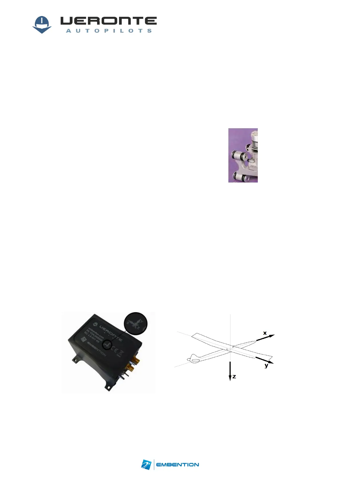
Veronte axes are printed on the box and aircraft coordinates are defined by the standard
aeronautical conventions.
Figure 6: Veronte & Aircraft Axis