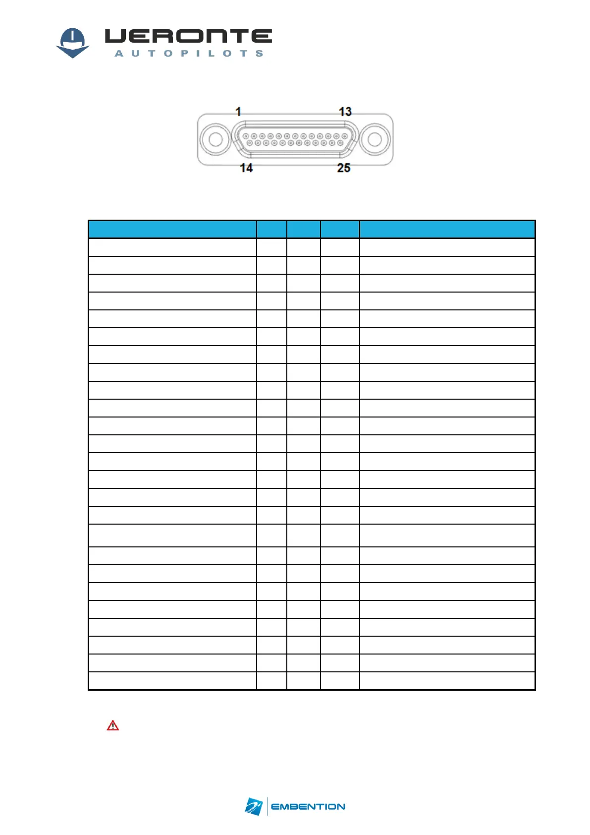
3.1.1. Expander I/O Signals
Figure 10: 25-pin Micro D for Veronte Expander (7) (Veronte connector view)
Different connections can be used depending on theselected hardware configuration.
Hardware option, not selectable on SW
Hardware option, not selectable on SW
ANALOGIC_UNIPOLAR_1/ANALOGIC_DIF_1+
Hardware option, not selectable on SW
ANALOGIC_UNIPOLAR_2/ANALOGIC_DIF_1-
Hardware option, not selectable on SW
ANALOGIC_UNIPOLAR_3/ANALOGIC_DIF_2+
Hardware option, not selectable on SW
Only for configurations with 2 or more
expansion modules
PWM1/ECAP6/ARINC_TX_A_OUT
Hardware option, not selectable on SW
PWM2/ECAP5/ARINC_TX_B_OUT
Hardware option, not selectable on SW
PWM3/ECAP1/ARINC_RX_B_OUT
Hardware option, not selectable on SW
PWM4/ECAP2/ARINC_RX_A_OUT
Hardware option, not selectable on SW
ANALOGIC_UNIPOLAR_4/ANALOGIC_DIF_2-
Hardware option, not selectable on SW
ANALOGIC_UNIPOLAR_5/ANALOGIC_DIF_3+
Hardware option, not selectable on SW
ANALOGIC_UNIPOLAR_6/ANALOGIC_DIF_3-
Hardware option, not selectable on SW
Table 8: ExpanderI/O interface
Caution!!Veronte Expander has an independent power input. It is required
only for configurations with more than one expansion module.