EasyManua.ls Logo

Embention Veronte - Veronte Standard I;O Signals

Embention Veronte
20 pages
Print Icon
To Next Page IconTo Next Page
To Previous Page IconTo Previous Page
Loading...
cod:
Veronte-HUM-v2.8.docx
pag:
10/20
3.1.2. Veronte I/O Signals
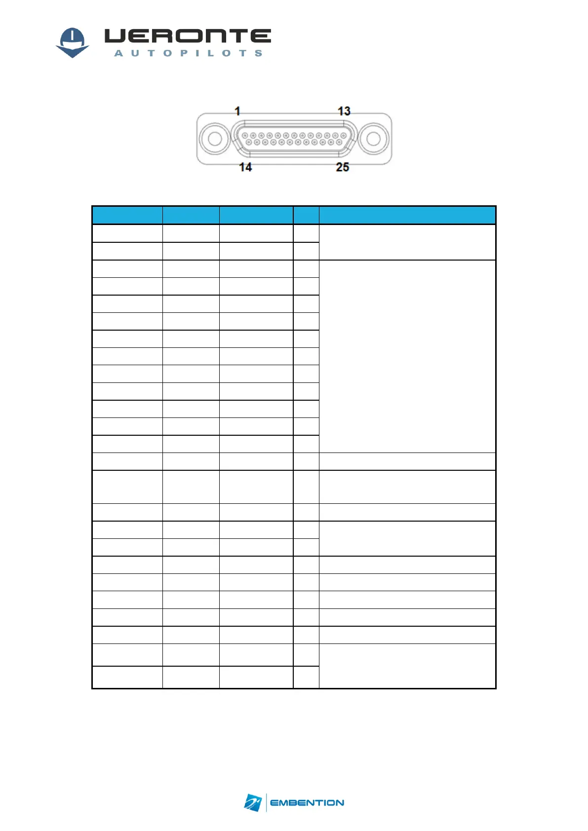
Figure 8: 25-pin Micro D connector for Veronte Autopilot I/O(4) (Veronte connector view)
Signal
Input
Output
Pin
Comments
VIN
Positive (+)
-
14
6.5 to 36V
GND1
Negative (-)
-
15
PWM/GPIO 1
-
5V (12mA)
1
Veronte offers the option to directly drive up
to 12 servos/ESCs with PWM outputs.
PWM rate goes from 50Hz up to 400Hz.
PWM rate is linked in pairs as follows:
1 & 7
2 & 8
3 & 9
4 & 10
5 & 11
6 & 12
Note: PWM11 can be used as FTS
independent logic output on demand.
PWM/GPIO 2
-
5V (12mA)
2
PWM/GPIO 3
-
5V (12mA)
3
PWM/GPIO 4
-
5V (12mA)
4
PWM/GPIO 5
-
5V (12mA)
5
PWM/GPIO 6
-
5V (12mA)
6
PWM/GPIO 7
-
5V (12mA)
7
PWM/GPIO 8
-
5V (12mA)
8
PWM/GPIO 9
-
5V (12mA)
20
PWM/GPIO 10
-
5V (12mA)
21
PWM11 (FTS)
-
3.3V (12mA)
16
GND2
-
-
9
GND for PWM111
PWM/GPIO 12
(DIGIN2)
4V to 9V
(on
demand)
5V (12mA)
23
Note: PWM12 can be used as a digital input
on demand (hardware option).
GND3
-
-
24
GND for PWM12 (GND DIGIN2)
RS232TX
-
±5V (35mA)
10
It supports baud rates up to 115200bps.
RS232RX
±25V
-
11
GND4
-
-
13
GND for RS232
DIGIN1
4V to 9V
-
12
CMOS/TTL with interrupt capability.
GND5
-
-
17
GND for DIGIN1
ADCIN1
0V to 36V
-
25
User-defined analog signal
GND6
-
-
18
GND for ADCIN1
CANHI
-7V to 12V
-7V to 12V
(50mA)
22
CANbus interface. It supports data rates up to
1 Mbps. Recommended cable is a twisted pair
with a 120Ω Zo.
CANLO
-7V to 12V
-7V to 12V
(50mA)
19
Table6: Veronte I/O interface (4)