Interpreting LED activity
37
Operating the DS-300B
Interpreting LED activity
System activity and status can be determined through the activity of
the LEDs on the switch.
There are three possible LED states: no light, a steady light, and a
flashing light. The steady lights and flashing lights can be green or
amber.
The LEDs flash either of these colors during boot, POST, or other
diagnostic tests. This is normal and does not indicate a problem
unless the LEDs do not indicate a healthy state after all boot processes
and diagnostic tests are complete.
The DS-300B has the following LEDs:
◆ system power LED
One LED (green) to indicate system power.
◆ system status LED
One LED (green/amber) to indicate system status.
◆ Ethernet status LEDs
Two LEDs to indicate speed and link status.
◆ port status LEDs
24 LEDs (green/amber) to indicate status for each port.
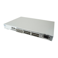
LED locations
All DS-300B LEDs are located on the port side.
Figure 3 on page 38 shows the LEDs on the DS-300B.