Appendix A: Cabling
EMC VNX8000 Hardware Information Guide 129
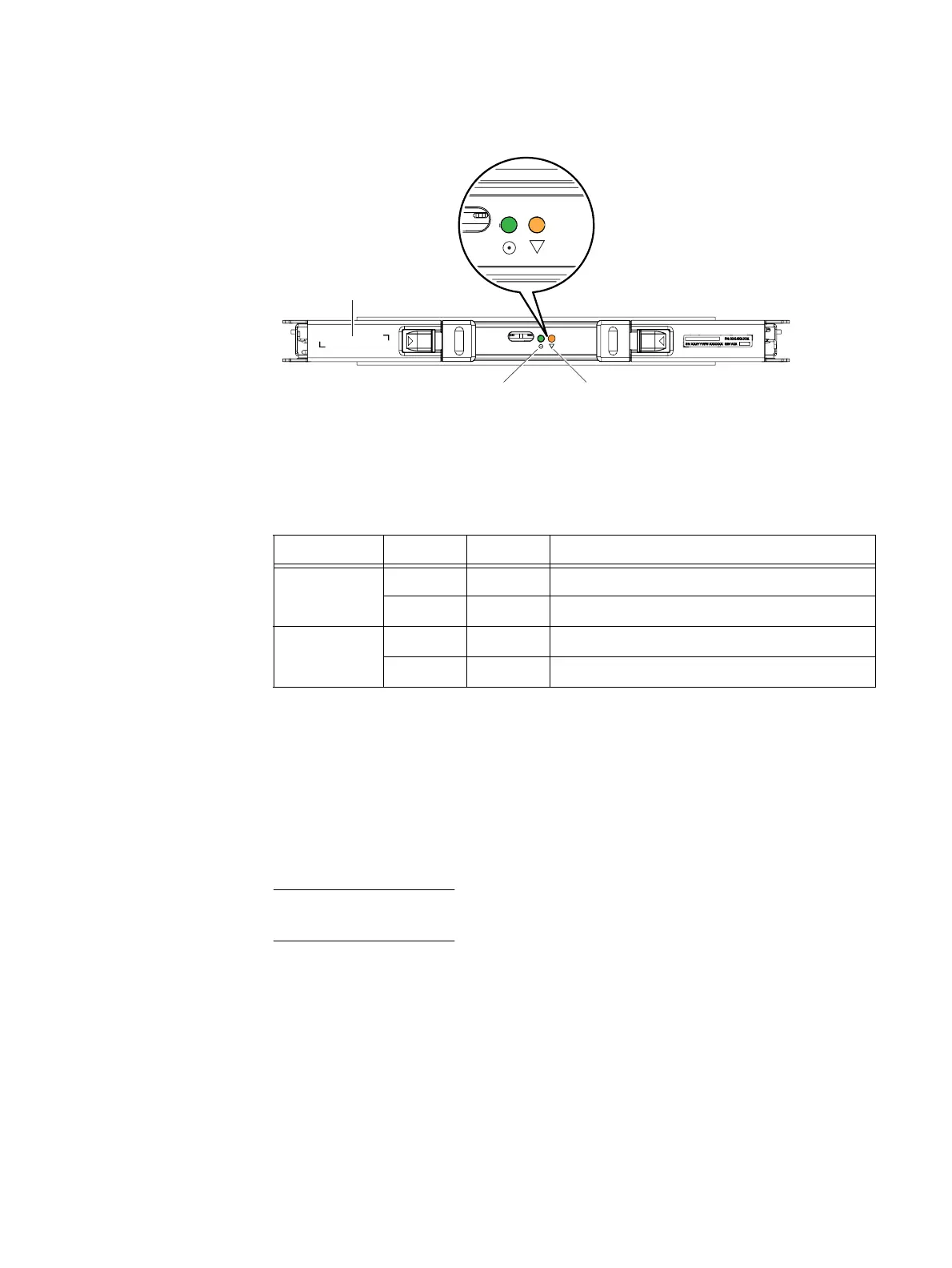
Figure 111 shows the location of the status LEDs on the 4U, 60 DAE LCC.
Figure 111 Example of a 4U, 60 (2.5- or 3.5-inch) DAE LCC A showing the status LEDs
Table 54 describes the 4U, 60 (2.5- or 3.5-inch) DAE LCC status LEDs.
Appendix A: Cabling
This section describes examples of the types of cabling you will need to connect the DAEs
to your VNX series platform. The descriptions are presented in illustrations and text. Each
illustration shows an example of the cable connection points (ports) located on the
specific hardware components for the VNX8000 platform.
The following sections only discuss the DAE cabling of the VNX8000 platform with either
the 3U, 15 disk drive DAE or the 2U, 25 disk drive DAE.
For all other cabling of your VNX8000 platform, the
VNX8000 Installation Guide
provides
information about
the SPE power cabling, DAE power cabling, PDU power cabling, LAN
cabling, and so on.
!
LCC A
Power fault LED (amber)
VNX-000654
Power LED (green)
Table 54 LCC status LED
Led Color State Description
Power Green On Power on
—OffPower off
Power fault Amber On Fault
— Off No fault or power off

 Loading...


