Disk-array enclosures
EMC VNX8000 Hardware Information Guide 97
Table 41 describes the 3U, 120 DAE status LEDs.
Rear view
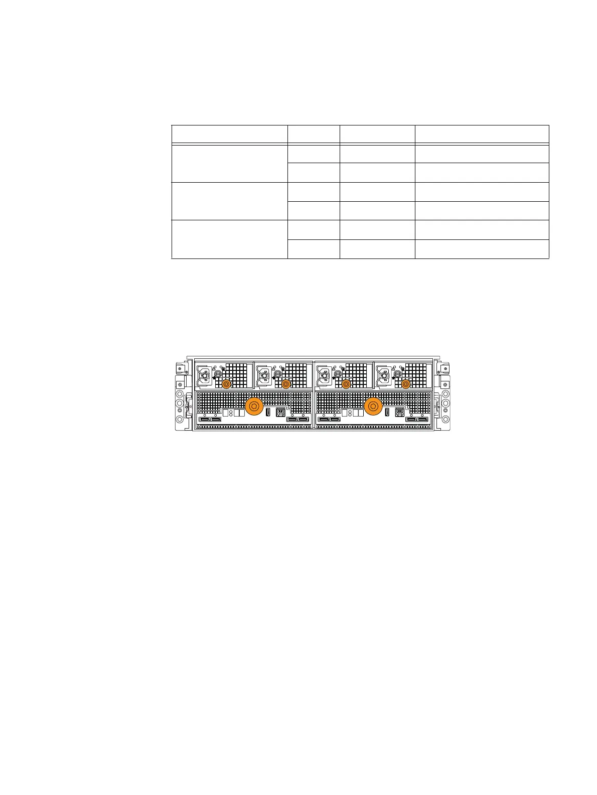
Figure 77 shows the 3U, 120 (2.5-inch) DAE includes two LCCs (A and B) and four power
supply modules.
Figure 77 Example of a 3U, 120 (2.5-inch) DAE with two LCCs (A and B) and four power supply
modules (locations A0, A1, B0, and B1)
The 3U, 120 (2.5-inch) DAE supports one type of power supply module: a dual DC output
power supply. Figure 77 shows the dual DC output power supplies having an orange knob
to install and remove the power supplies to and from the enclosure.
Power supply module
As shown in Figure 77, the power supply module is described in the following paragraphs.
For more information about the technical specifications of the single and the dual output
power supplies, go to https://mydocs.emc.com/VNX/, select View technical
specifications. Next, follow the steps in the wizard for your desired technical
specification. For information about replacing a power supply module, go to
Replacing a
power supply module in a 120-disk enclosure
procedure available online at
https://mydocs.emc.com/VNX/ and go to VNX Tasks,
then select Replace VNX hardware.
Next, follow the steps in the wizard.
Table 41 3U, 120 DAE status LEDs
LED Color State Description
SSC fault (see location A in
Figure 76 on page 96)
Amber On Fault detected
— Off No fault detected
DAE fault (see location B in
Figure 76 on page 96)
Amber On Fault detected
— Off No fault detected
DAE power Blue On Powered on, normal
Off Not powered on or fault
LCC ALCC B
A0B0 B1 A1

 Loading...


