8 EMC VNX5400 Hardware Information Guide
VNX5400 product description
Rear view
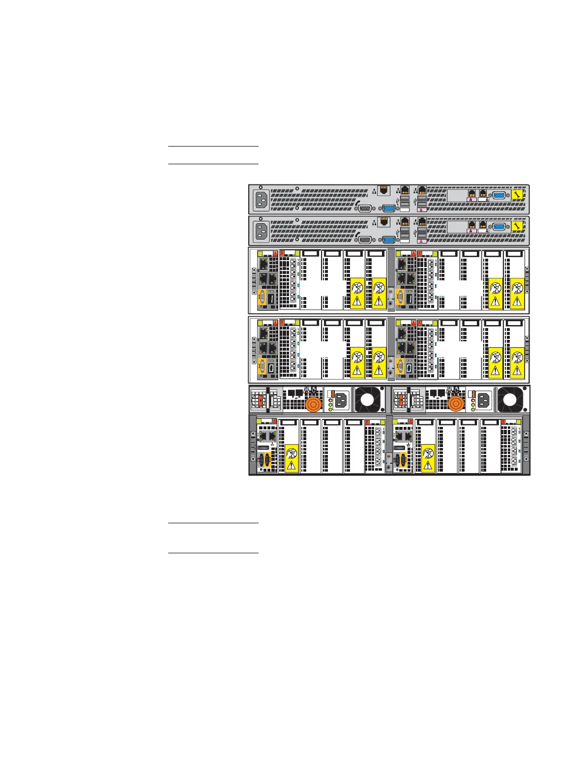
Figure 2 shows an example of the rear view of a File/Unified VNX5400 platform having a
3U DPE showing two storage processors (SP A and B), two 2U Data Mover enclosures with
four Data Movers, and two 1U Control Stations (one optional).
Note: The example shown in Figure 2 does not show any DAEs.
Figure 2 Example of a File/Unified VNX5400 platform (rear view)
Note: Figure 1 on page 7 and Figure 2 are examples of a File/Unified VNX5400 platform
(front and rear views) without any DAEs. These figures are for illustrative purposes only.
Control Station 1
(optional)
Data Mover
enclosure 0
Disk processor
enclosure
Control Station 0
0
123
0
123
AC
DC
!
1
0
1
0
X4
AC
DC
!
X4
X4
X4
0
123
0
123
B MGMT
MGMT
B
CS
A
1
2
MGMT
IOIO
B MGMT
MGMT
B
CS
A
1
2
MGMT
IOIO
Data Mover
enclosure 1
0
123
0
123
Data Mover 5
Data Mover 2Data Mover 3
Data Mover 4
VNX-000941

 Loading...


