System component description
EMC VNX5400 Hardware Information Guide 23
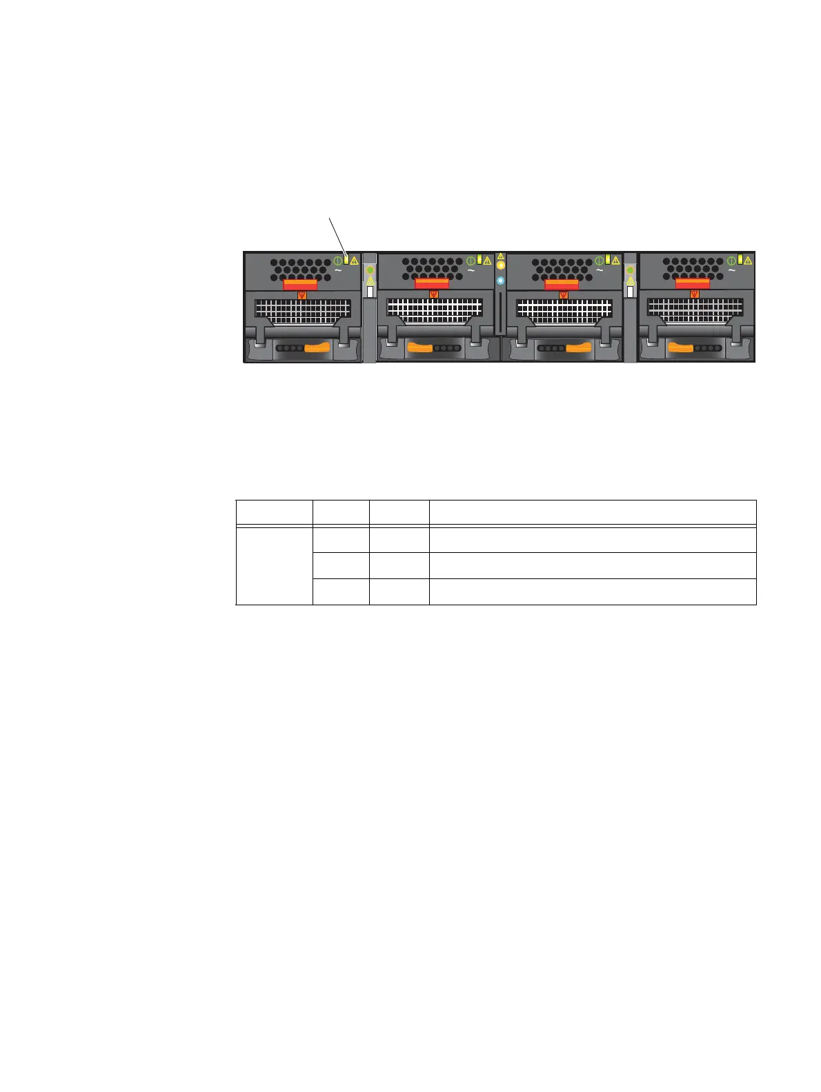
Power supply/cooling (fan) module LED
The power supply/cooling (fan) modules have status LED on the front. Figure 9 shows the
LEDs for the power supply/cooling (fan) modules.
Figure 9 Power supply/cooling (fan) module LED
Table 7 describes the power supply/cooling (fan) LED.
VNX5400 rear view
As previously described, the File/Unified VNX5400 platform is made up of a 3U DPE, two
1U Control Stations (one optional), and one to two 2U Data Mover enclosures having one
to two Data Movers. The following sections will describe the rear view of the VNX5400
platform components as previously shown in Figure 2 on page 8.
DPE rear view
Figure 10 on page 26 shows an example of the rear of the 3U DPE. The following modules,
connectors, status LEDs, and latch handles are described:
◆ Battery backup unit (BBU), two (one for each SP)
◆ Base module, two (one for each SP)
• Two 6 Gb/s mini-SAS HD ports (looking from the left, they are labeled 1 and 0,
respectively). Below each mini-SAS HD port, the ports are labeled x4. To the left of
mini-SAS HD port 1, the ports are vertically labeled 6 Gb SAS.
• Two LEDs (fault and unsafe to remove)
AC
AC
AC
AC
Power supply/
cooling (fan) power/fault LED
CNS-001673
Table 7 Power supply/cooling (fan) module LED
LED Color State Description
Power/Fault Green On Normal (no faults detected)
Amber Blinking Power supplied but external fault detected
Amber On No power

 Loading...


