Menu 12 Introduction
Parameter
x.00
Parameter
description format
Keypad and
display
Serial
communications
CT Modbus
RTU
PLC Ladder
programming
CTSoft Menu 0
Advanced parameter
descriptions
162 Commander SK Advanced User Guide
www.controltechniques.com Issue Number: 9
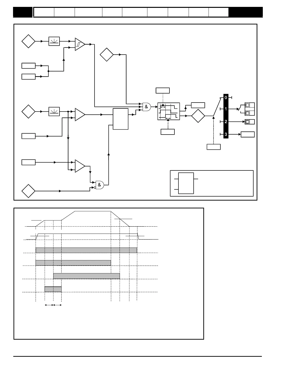
Figure 10-40 Brake function diagram
Figure 10-41 Brake sequence
Current
magnitude
Brake release
current threshold
Brake apply
current threshold
12.42
12.43
+
_
Motor
frequency
Brake release
frequency
Brake apply
frequency
12.44
12.45
+
_
+
_
Reference
enabled
Latch
Drive
active
In
Out
Reset
Pre-brake
release
delay
12.46
Post brake
release
delay
12.47
Brake
release
Brake
controller
enable
12.41
T5
T6
B3
User
programmable
Brake
disabled
Ramp
hold
4.01
5.01
1.11
10.02
2.03
12.40
Latch
In
Out
Reset
If the reset input is 1, the output is 0
If the reset input is 0, the output
latches at 1 if the input is 1
1.11
Pr Brake release
12.40
Pr Ramp hold
2.03
Pr Drive active
10.02
4.01
1. Wait for brake release current threshold and brake release frequency
2. Pre-brake release delay
3. Post-brake release delay
4. Wait for brake apply frequency
5. Wait for zero frequency
6. 1s delay as phase 2 of stopping sequence (Pr =1,2 or 3)
6.01
Pr Brake release frequency
12.44
Pr Brake apply frequency
12.45
Pr
12.46
Pr
12.47
Pr Brake release current threshold
12.42
Pr Brake apply current threshold
12.43