Introduction
Parameter
x.00
Parameter
description format
Keypad and
display
Serial
communications
CT Modbus
RTU
PLC Ladder
programming
CTSoft Menu 0
Advanced parameter
descriptions
Menu 21
Commander SK Advanced User Guide 195
Issue Number: 9 www.controltechniques.com
When this parameter is set to On(1), it signifies that motor map 2 is active.
This parameter can be programmed to a digital output to give a signal to an external circuit to close a second motor contactor when motor map 2
becomes active.
Pr 21.16 works in conjunction with Pr 4.16 and Pr 4.25. The motor protection modes set-up by Pr 4.16 and Pr 4.25 for motor 1 will be used for motor
2 but the thermal time constant for motor 2 will be defined in Pr 21.16.
See Pr 4.16 on page 68 and Pr 4.25 on page 71 for further details.
This parameter defines the current limit as a percentage of the rated active current. When the motor rated current is set lower than the drive rated
current, the maximum value of this parameter increases to allow larger overloads.
Therefore, by setting the motor rated current to a lower value than the drive rated current, it is possible to have a current limit greater than 165%. An
absolute maximum current limit of 999.9% is applied.
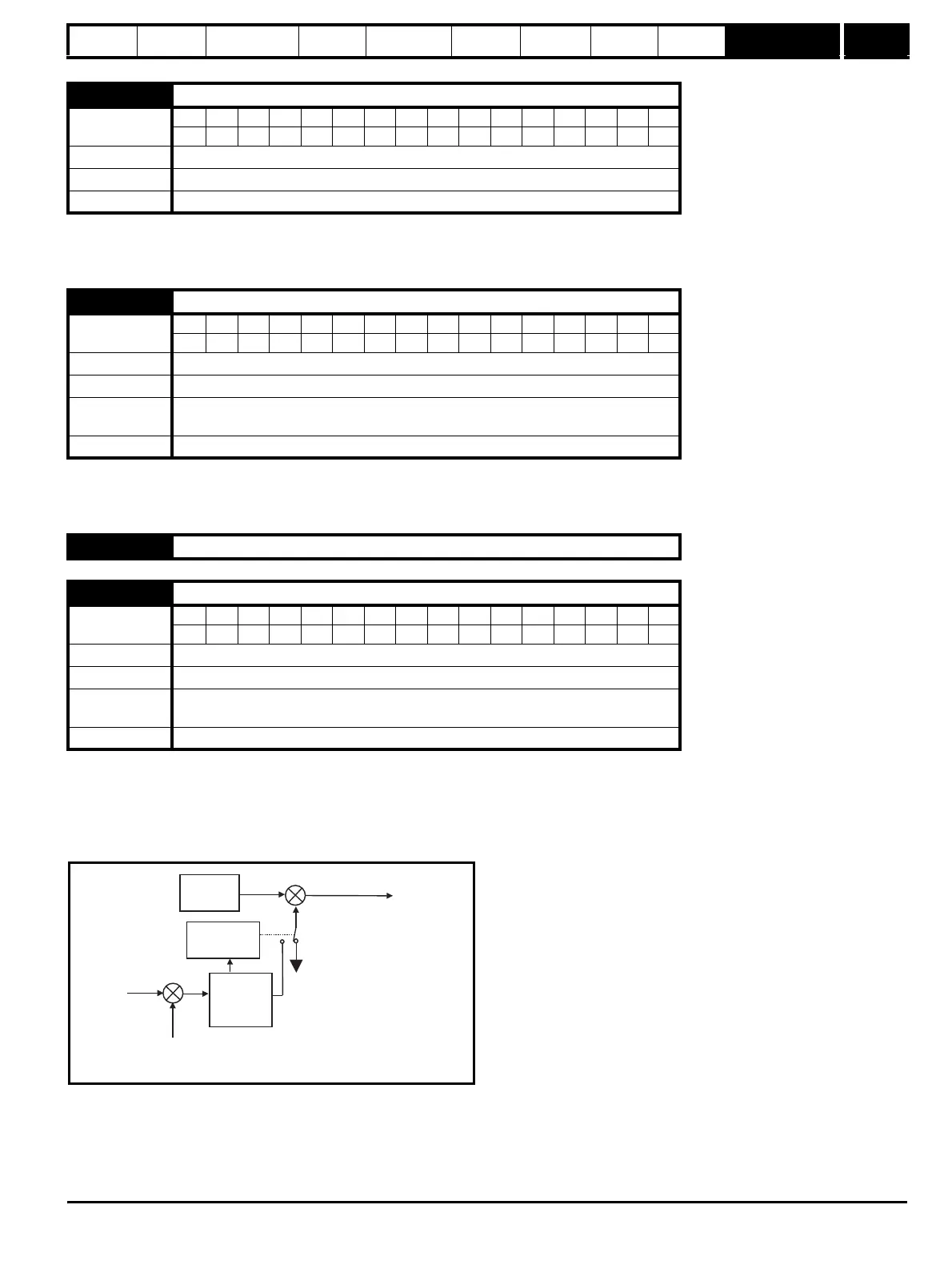
In frequency control mode (Pr 4.11 = OFF), the drive output frequency is modified if necessary to keep the active current within the current limits as
shown in the following diagram:
The active current limit is compared with the active current and if the current exceeds the limit the error value passes through the PI controller to give
a frequency component which is used to modify the ramp output. The direction of the modification is always to reduce the frequency to zero if the
active current is motoring, or to increase the frequency towards the maximum if the current is regenerating. Even when the current limit is active the
ramp still operates, therefore the proportional and integral gains (Pr 4.13 and Pr 4.14) must be high enough to counter the effects of the ramp. For
method of setting the gains see Pr 4.13 and Pr 4.14 on page 67.
In torque control mode the current demand is limited by the active current limit. For operation of this mode see Pr 4.11 on page 66.
21.15 Motor 2 active
Coding
Bit SP FI DE Txt VM DP ND RA NC NV PT US RW BU PS
1111
Range OFF(0) or On(1)
Default OFF(0)
Update rate Background
21.16 Motor 2 thermal time constant
Coding
Bit SP FI DE Txt VM DP ND RA NC NV PT US RW BU PS
111
Range 0 to 250 s
Default 89
First motor
parameter
Pr 4.15
Update rate Background
21.17 to 21.28 Unused parameters
21.29 Motor 2 symmetrical current limit
Coding
Bit SP FI DE Txt VM DP ND RA NC NV PT US RW BU PS
11 1 111
Range 0 to MOTOR2_CURRENT_LIMIT_MAX %
Default 165.0
First motor
parameter
Pr 4.07
Update rate Background
PPr4.13
IPr4.14
Current limit
active
1
0
Active
current
limit
Post ramp
reference
Ramp
Active
current
-
+