Introduction
Parameter
x.00
Parameter
description format
Keypad and
display
Serial
communications
CT Modbus
RTU
PLC Ladder
programming
CTSoft Menu 0
Advanced parameter
descriptions
Menu 7
Commander SK Advanced User Guide 105
Issue Number: 9 www.controltechniques.com
In modes 2 and 3, a current loop loss trip (cL1) will be generated if the current input falls below 3mA.
If 4-20 or 20-4 modes are selected and the drive trips on current loop loss (cL1), analog reference 2 cannot be selected if the current reference is less
than 3mA.
If 4-.20 or 20-.4 modes are selected, Pr 7.28 will switch from OFF to On to indicate that the current reference is less than 3mA.
If both analog inputs (A1 and A2) are to be set-up as voltage inputs, and if the potentiometers are supplied from the drive’s +10V rail (terminal T3),
they must have a resistance >4kΩ.
This parameter is used to scale the analog input if so desired. However in most cases it is not necessary as each input is automatically scaled such
that for 100.0%, the destination parameters (defined by the settings of Pr 7.10 and Pr 7.14) will be at maximum.
This parameter can be used to invert the analog input reference (i.e. multiply the input scaling result by -1).
As default, this parameter is set-up automatically according to the drive configuration (see Pr 11.27 on page 140).
Only parameters which are not protected can be controlled by analog inputs. If a non valid parameter is programmed to the destination of an analog
input, the input is not routed anywhere.
After a modification to this parameter, the destination is only changed when a reset is performed.
Value Display Function
0 0-20 0 to 20mA
1 20-0 20 to 0mA
2 4-20 4 to 20mA with trip on loss
3 20-4 20 to 4mA with trip on loss
4 4-.20 4 to 20mA with no trip on loss
5 20-.4 20 to 4mA with no trip on loss
6 VoLt 0 to +10 volts
7.07 Unused parameter
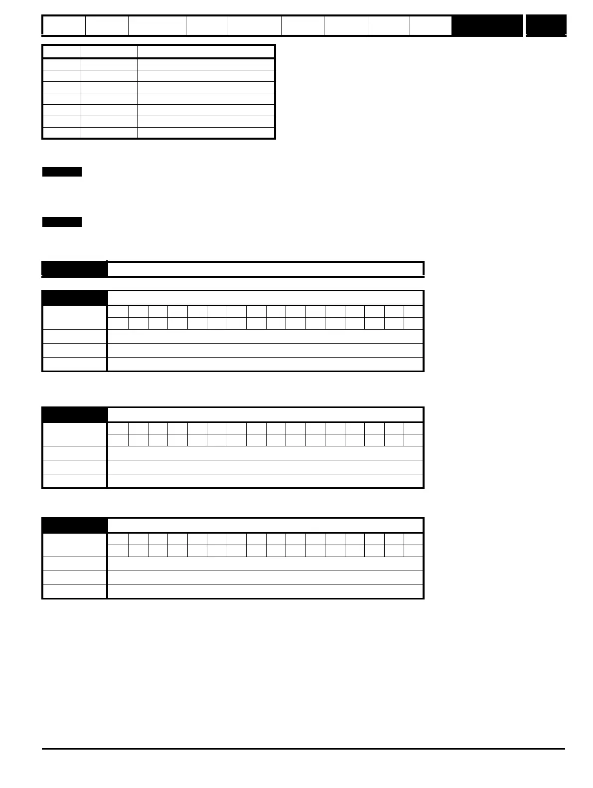
7.08 Analog input 1 scaling
Coding
Bit SP FI DE Txt VM DP ND RA NC NV PT US RW BU PS
3 111
Range 0.000 to 4.000
Default 1.000
Update rate Background
7.09 Analog input 1 invert
Coding
Bit SP FI DE Txt VM DP ND RA NC NV PT US RW BU PS
111
Range OFF(0) or On(1)
Default OFF(0)
Update rate 5 ms
7.10 Analog input 1 destination
Coding
Bit SP FI DE Txt VM DP ND RA NC NV PT US RW BU PS
1 2 1111
Range Pr 0.00 to Pr 21.51
Default Pr 1.36
Update rate Read on drive reset