Introduction
Parameter
x.00
Parameter
description format
Keypad and
display
Serial
communications
CT Modbus
RTU
PLC Ladder
programming
CTSoft Menu 0
Advanced parameter
descriptions
Menu 10
Commander SK Advanced User Guide 135
Issue Number: 9 www.controltechniques.com
This parameter defines the time period that the braking resistor installed can withstand full braking volts without damage. The setting of this parameter
is used in determining the braking overload time.
This parameter defines the time period which must elapse between consecutive braking periods of maximum braking power as defined by Pr 10.30.
The setting of this parameter is used in determining the thermal time constant of the resistor installed. It is assumed that the temperature will fall by
99% in this time, and so the time constant is Pr 10.30 / 5. If either Pr 10.30 or Pr 10.31 are is set to 0 then no braking resistor protection is
implemented.
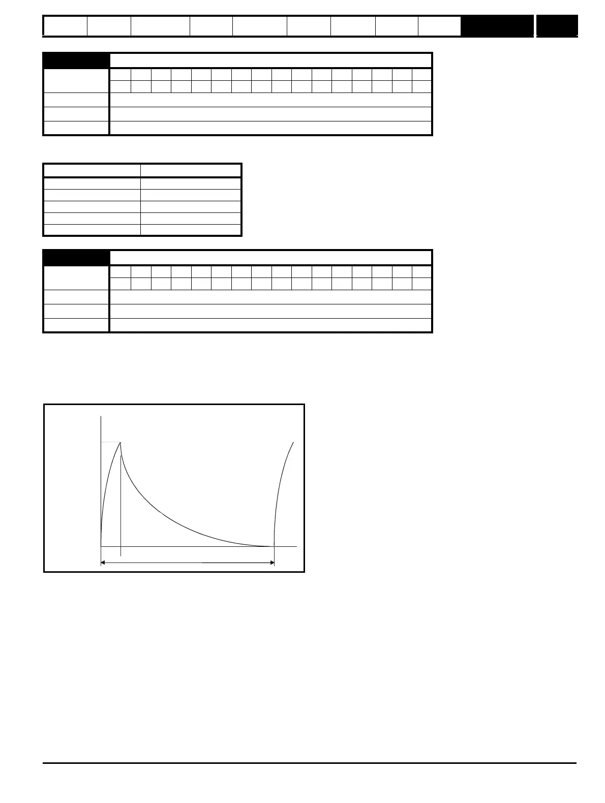
The braking resistor temperature is modelled by the drive as shown below. The temperature rises in proportion to the power flowing into the resistor
and falls in proportion to the difference between the resistor temperature and ambient.
Assuming that the full power braking time is much shorter than the full power braking period (which is normally the case) the values for Pr 10.30 and
Pr 10.31 can be calculated as follows:
Power flowing into the resistor when the braking IGBT is on, Pon = Full braking volts
2
/ R
Where:
Full braking volts is defined in the table (see Pr 10.30) and R is the resistance of the braking resistor.
Full power braking time (Pr 10.30), T
on
= E / P
on
Where:
E is the total energy that can be absorbed by the resistor when its initial temperature is ambient temperature.
Therefore full power braking time (Pr 10.30), T
on
= E x R / Full braking volts
2
If the cycle shown in the diagram previously is repeated, where the resistor is heated to its maximum temperature and then cools to ambient:
The average power in the resistor P
av
= P
on
x T
on
/ Tp
Where:
Tp is the full power braking period
P
on
= E / T
on
Therefore P
av
= E / Tp
10.30 Full power braking time
Coding
Bit SP FI DE Txt VM DP ND RA NC NV PT US RW BU PS
2 111
Range 0.00 to 320.00 s
Default 0.00
Update rate Background
Drive voltage rating Full braking volts
110V 390V
200V 390V
400V 780V
575V 930V
690V 1120V
10.31 Full power braking period
Coding
Bit SP FI DE Txt VM DP ND RA NC NV PT US RW BU PS
1 111
Range 0.0 to 1500.0 s
Default 0.0
Update rate Background
0
100
%
t
Pr
10.30
Pr
10.31
Overload
accumulator
Pr
10.39