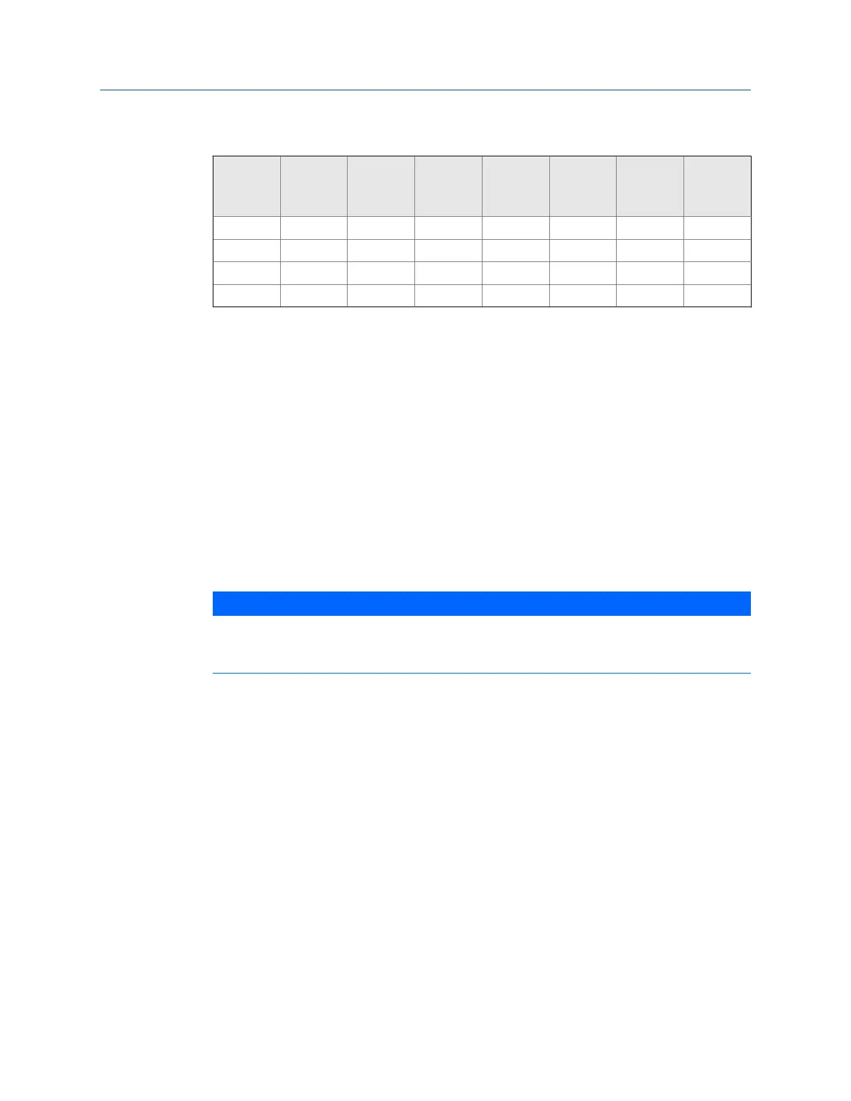
Configurations for open collector frequency outputs (continued)Table 3-1:
Cable
Cable re-
sistance Cable
Pull-up
resist-
ance Total
Maxi-
mum fre-
quency Sink
Cable
voltage
drop
0.5 16.8 10.00 500 516.8 5000 0.046 0.780
1 33.6 20.00 500 533.6 5000 0.045 1.511
1.7 57.12 34.00 500 557.12 5000 0.043 2.461
6.5 218.4 130.00 500 718.4 1000 0.033 7.296
The 22 AWG wire characteristics:
• Capacitance = 20 pF/ft or 20 nF/1000 ft (between two wires)
• Resistance = 0.0168 Ohms/ft or 16.8 Ohms/1000 ft
• Pull-up voltage = 24 VDC
3.3 Grounding meter electronics housing
The meter electronics should be internally grounded for intrinsically safe operations.
Connect a wire to the chassis ground lug installed inside the Transmitter Electronics
Enclosure as the primary ground. A secondary ground is located outside of the Transmitter
Electronics Enclosure (see ).
NOTICE
The internal grounding terminal shall be used as the primary equipment ground. The external
terminal is only a supplemental bonding connection where local authorities permit or require
such a connection. DO NOT connect digital grounds to the ground lugs.
Electrical installation
46 Gas Ultrasonic Flow Meter

 Loading...


