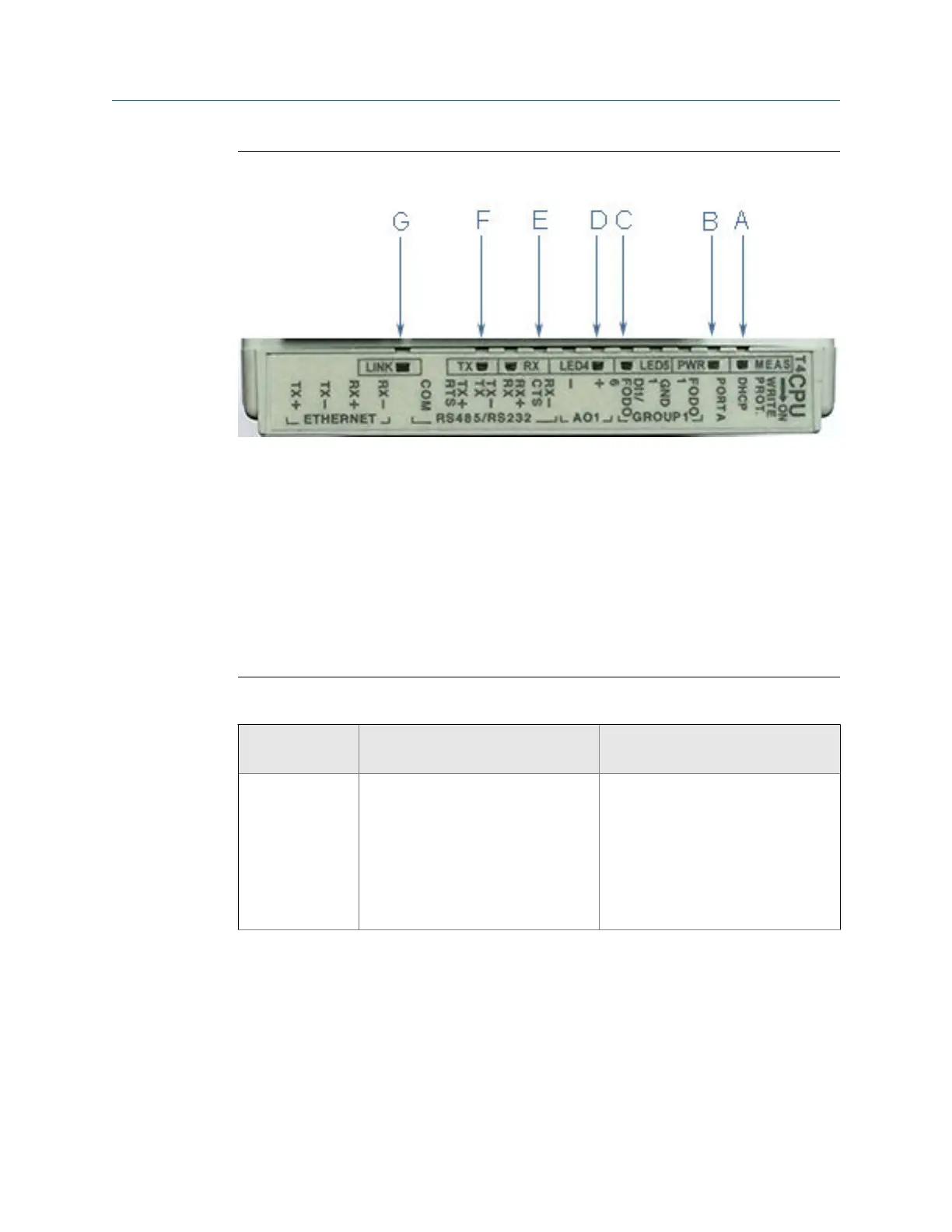
CPU Module labeling and LED indicators - Type 4Figure 3-8:
A. Acquisition/Measurement mode
B. Power
C. LED 5 - communication between CPU and Acquisition Module
D. LED 4 - link between CPU and Acquisition Module
E. RX (RS-485/RS-232) - receiving data
F. TX (RS-485/RS-232) - transmitting data (RS-485 2-wire use TX+ and TX-)
G. Link (Eth1 Link) - user Ethernet connection
CPU Module labeling and LED functionsTable 3-2:
CPU Module la-
bel or LED Function Switch position indicator or LED
WRITE PROT. • Write-protect mode - with switch
in the ON position (default set-
ting) protects configuration and
firmware overwrites.
• To write configuration changes or
download firmware to the meter
change the switch to the OFF posi-
tion
Switch position
• ON - (default setting) enables
write protection of the configura-
tion and firmware
• OFF - enables writing configura-
tion changes or downloading firm-
ware
Electrical installation
Installation manual 57

 Loading...


