24 Digitax ST Installation Guide
www.controltechniques.com Issue: 2
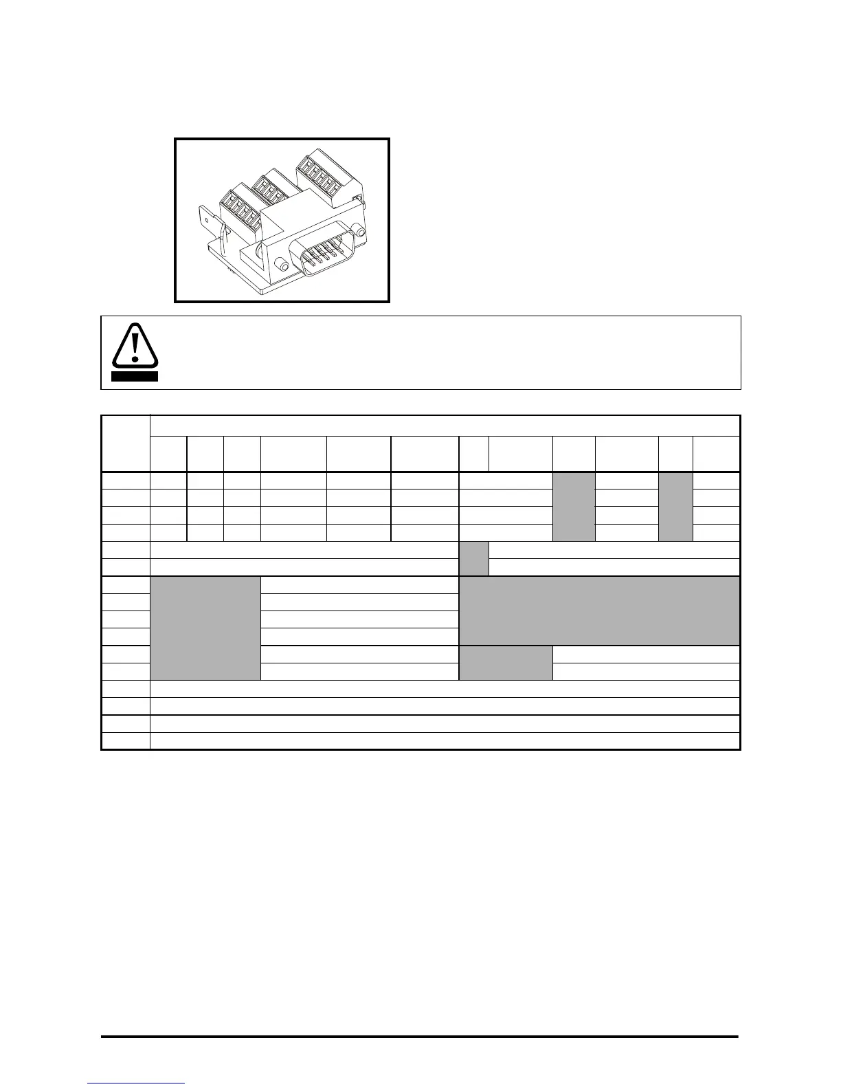
Drive encoder input converter connector
A 15-way D-type converter is available to provide a screw terminal interface for encoder
wiring, and a spade terminal for the shield.
Figure 4-13 Drive encoder input converter connector
Table 4-3 Encoder In connector details
* Marker pulse is optional
** The encoder supply is selectable through parameter configuration to 5Vdc, 8Vdc
and 15Vdc
*** Terminal 15 is a parallel connection to T8 analog input 3. If this is to be used as a
thermistor input, ensure that Pr 7.15 is set to ‘th.sc’ (7), ‘th’ (8) or ‘th.diSP’ (9)
If using the drive encoder input converter connector protection to at least IP2X must be
provided for the connector.
WARNING
Term.
Setting of Pr 3.38
Ab
(0)
Fd
(1)
Fr
(2)
Ab.SErVO
(3)
Fd.SErVO
(4)
Fr.SErVO
(5)
SC
(6)
SC.HiPEr
(7)
EndAt
(8)
SC.EndAt
(9)
SSI
(10)
SC.SSI
(11)
1AFF A F F Cos
Cos Cos
2 A\ F\ F\ A\ F\ F\ Cosref Cosref Cosref
3 B D R B D R Sin Sin Sin
4 B\ D\ R\ B\ D\ R\ Sinref Sinref Sinref
5Z*
Encoder input - Data (input/output)
6 Z\* Encoder input - Data\ (input/output)
7
U
8U\
9V
10 V\
11 W
Encoder input - Clock (output)
12 W\ Encoder input - Clock\ (output)
13 +V**
14 0V common
15 th***
Shell 0V common
 Loading...


