Digitax ST Installation Guide 25
Issue: 2 www.controltechniques.com
Safety Information Introduction Mechanical Installation
Electrical Installation
Table 4-4 Simulated encoder output connector details
Digitax ST Plus additional connections
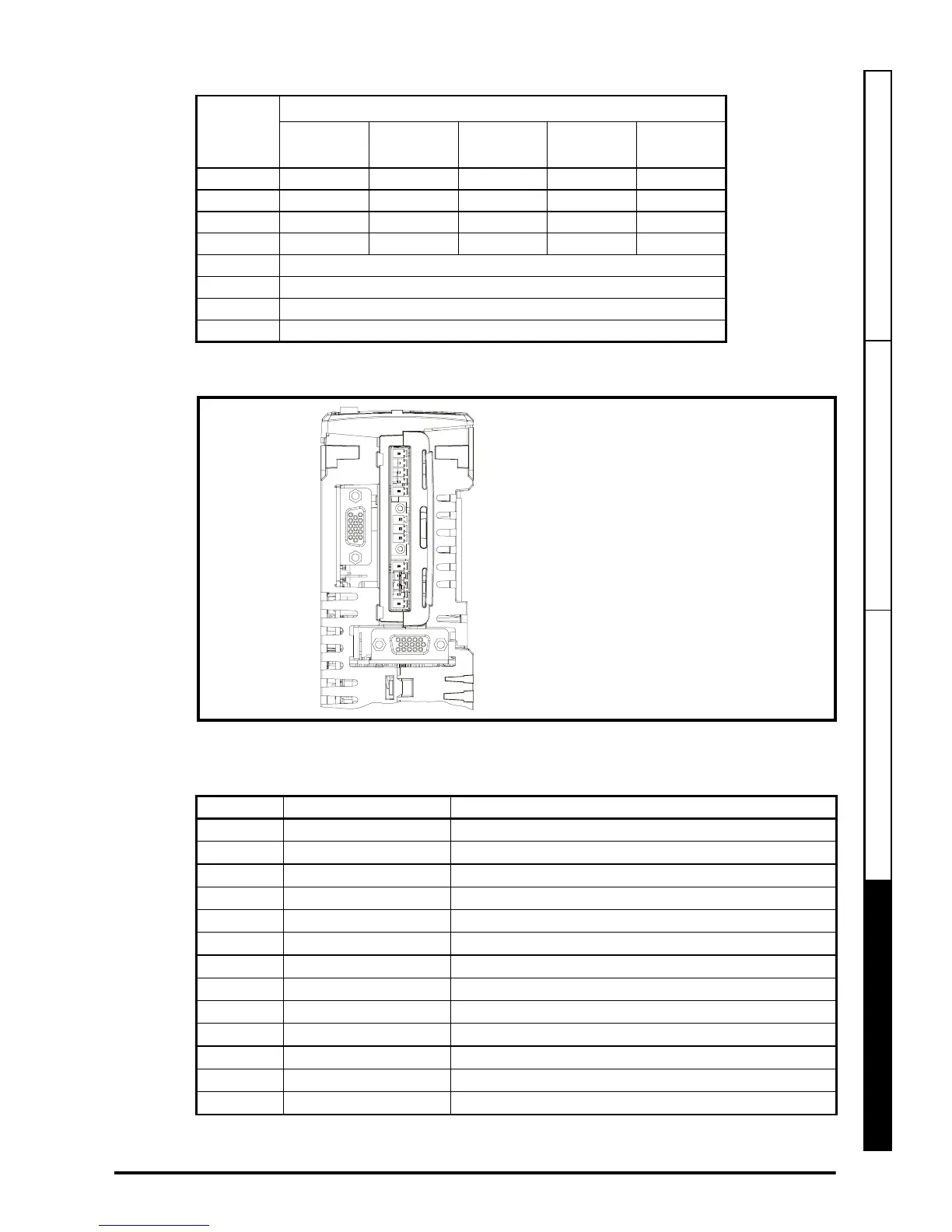
Figure 4-14 Digitax ST Plus terminals view
The terminals are numbered from terminal 1 at the top, to terminal 13 at the bottom as
per the orientation shown in Figure 4-14. The terminal functions are given in Table 4-5:
Table 4-5 Digitax ST Plus connector details
Term.
Setting of Pr 3.54
Ab
(0)
Fd
(1)
Fr
(2)
Ab.L
(3)
Fd.L
(4)
1A F F A F
2A\F\F\A\F\
3BDRBD
4B\D\R\B\D\
5Z*
6Z\*
14 0V
Shell 0V common
Terminal Function Description
1 0V SC 0V connection for EIA-RS485 port
2 /RX EIA-RS485 Receive line (negative). Incoming.
3 RX EIA-RS485 Receive line (positive). Incoming.
4 /TX EIA-RS485 Transmit line (negative). Outgoing.
5 TX EIA-RS485 Transmit line (positive). Outgoing.
6 Fieldbus Type A Fieldbus Type data line
7 Fieldbus Type Shield Shield connection for Fieldbus Type
8 Fieldbus Type B Fieldbus Type data line
9 0V 0V connection for digital I/O
10 DI0 Digital input 0
11 DI1 Digital input 1
12 DO0 Digital output 0
13 DO1 Digital output 1
1
13
Connector specification:
Maximum size cable = 1.5mm
2
Torque = 0.2 N m (1.8 lb in)
 Loading...


