Safety
Information
Product
information
Mechanical
installation
Electrical
installation
Getting
started
Basic
parameters
Running the
motor
Optimization
EtherCAT
interface
SMARTCARD
Operation
Onboard
PLC
Advanced
parameters
Technical
Data
Diagnostics
UL listing
information
Digitax ST User Guide 151
Issue Number: 5
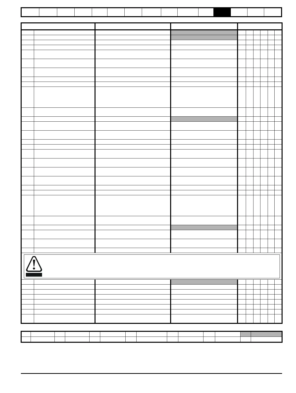
Parameter
Range(
Ú) Default(Ö)
Type
12.01 Threshold detector 1 output OFF (0) or On (1) RO Bit NC PT
12.02 Threshold detector 2 output OFF (0) or On (1)
RO Bit NC PT
12.03 Threshold detector 1 source Pr 0.00 to 21.51 Pr 0.00 RW Uni PT US
12.04 Threshold detector 1 level 0.00 to 100.00 % 0.00 RW Uni US
12.05
Threshold detector 1
hysteresis
0.00 to 25.00 % 0.00 RW Uni US
12.06
Threshold detector 1 output
invert
OFF (0) or On (1) OFF (0) RW Bit US
12.07
Threshold detector 1
destination
Pr 0.00 to 21.51 Pr 0.00 RW Uni DE PT US
12.08 Variable selector 1 source 1 Pr 0.00 to 21.51 Pr 0.00 RW Uni PT US
12.09 Variable selector 1 source 2 Pr 0.00 to 21.51 Pr 0.00 RW Uni PT US
12.10 Variable selector 1 mode
Select input 1 (0), select input 2 (1), add (2),
subtract (3), multiply (4), divide (5),
filter (6), linear ramp (7), absolute value (8),
powers (9), sectional control (10),
external rectifier monitor (11)
Select input 1 (0) RW Uni US
12.11
Variable selector 1
destination
Pr 0.00 to 21.51 Pr 0.00 RW Uni DE PT US
12.12 Variable selector 1 output ±100.00 %
RO Bi NC PT
12.13
Variable selector 1 source 1
scaling
±4.000 1.000 RW Bi US
12.14
Variable selector 1 source 2
scaling
±4.000 1.000 RW Bi US
12.15 Variable selector 1 control 0.00 to 100.00 s 0.00 RW Uni US
12.23 Threshold detector 2 source Pr 0.00 to 21.51 Pr 0.00 RW Uni PT US
12.24 Threshold detector 2 level
0.00 to 100
.00 %
0.00 RW Uni US
12.25
Threshold detector 2
hysteresis
0.00 to 25.00 % 0.00 RW Uni US
12.26
Threshold detector 2 output
invert
OFF (0) or On (1) OFF (0) RW Bit US
12.27
Threshold detector 2
destination
Pr 0.00 to 21.51 Pr 0.00 RW Uni DE PT US
12.28 Variable selector 2 source 1 Pr 0.00 to 21.51 Pr 0.00 RW Uni PT US
12.29 Variable selector 2 source 2 Pr 0.00 to 21.51 Pr 0.00 RW Uni PT US
12.30 Variable selector 2 mode
Select input 1 (0), select input 2 (1), add (2),
subtract (3), multiply (4), divide (5),
filter (6), linear ramp (7), absolute value (8),
powers (9), sectional control (10),
external rectifier monitor (11)
Select input 1 (0) RW Uni US
12.31
Variable selector 2
destination
Pr 0.00 to 21.51 Pr 0.00 RW Uni DE PT US
12.32 Variable selector 2 output ±100.00 %
RO Bi NC PT
12.33
Variable selector 2 source 1
scaling
±4.000 1.000 RW Bi US
12.34
Variable selector 2 source 2
scaling
±4.000 1.000 RW Bi US
12.35 Variable selector 2 control 0.00 to 100.00 s 0.00 RW Uni US
12.40 Brake release indicator OFF (0) or On (1)
RO Bit NC PT
12.41 Brake controller enable dis (0), rEL (1), d IO (2), USEr (3) dis (0) RW Txt US
12.43 Lower current threshold 0 to 200 % 10 RW Uni US
12.45 Brake apply speed 0 to 200 rpm 5 RW Bit US
12.46 Brake apply speed delay 0.0 to 25.0 s 1.0 RW Uni US
12.47 Post brake release delay 0.0 to 25.0 s 1.0 RW Uni US
12.48 Brake apply delay 0.0 to 25.0 s 1.0 RW Uni US
12.49
Enable position controller
during brake release
OFF (0) or On (1) OFF (0) RW Bit US
The brake control functions are provided to allow well co-ordinated operation of an external brake with the drive. While both hardware
and software are designed to high standards of quality and robustness, they are not intended for use as safety functions, i.e. where a
fault or failure would result in a risk of injury. In any application where the incorrect operation of the brake release mechanism could
result in injury, independent protection devices of proven integrity must also be incorporated.
RW Read / Write RO Read only Uni Unipolar Bi Bi-polar Bit Bit parameter Txt Text string
FI Filtered DE Destination NC Not copied RA Rating dependent PT Protected US User save PS Power down save

 Loading...


