Safety
Information
Product
information
Mechanical
installation
Electrical
installation
Getting
started
Basic
parameters
Running the
motor
Optimization
EtherCAT
interface
SMARTCARD
Operation
Onboard
PLC
Advanced
parameters
Technical
Data
Diagnostics
UL listing
information
180 Digitax ST User Guide
Issue Number: 5
PVC insulated cable should be used.
Installation class (ref: IEC60364-5-52:2001)
B1 - Separate cables in conduit.
B2 - Multicore cable in conduit
C - Multicore cable in free air.
Cable sizes are from IEC60364-5-52:2001 table A.52.C with correction
factor for 40 °C ambient of 0.87 (from table A52.14) for cable installation
method B2 (multicore cable in conduit).
Cable size may be reduced if a different installation method is used, or if
the ambient temperature is lower.
The recommended cable sizes above are only a guide. The mounting
and grouping of cables affects their current-carrying capacity, in some
cases smaller cables may be acceptable but in other cases a larger
cable is required to avoid excessive temperature or voltage drop. Refer
to local wiring regulations for the correct size of cables.
N
The recommended output cable sizes assume that the motor maximum
current matches that of the drive. Where a motor of reduced rating is
used the cable rating may be chosen to match that of the motor. To
ensure that the motor and cable are protected against overload, the
drive must be programmed with the correct motor rated current.
N
UL listing is dependent on the use of the correct type of UL-listed fuse,
and applies when symmetrical short-circuit current does not exceed 100
kA. See Chapter 15 UL listing information on page 204 for sizing
information.
An MCB (miniature circuit breaker) may be used in place of fuses under
the following conditions:
• The fault-clearing capacity must be sufficient for the installation
• The I
2
T rating of the MCB must be less than or equal to that of the fuse
rating listed above.
A fuse or other protection must be included in all live connections to the
AC supply.
For a parallel DC bus system the maximum AC input fusing is shown in
Table 13-20 below.
Table 13-20 Maximum AC input fusing
Refer to the supplier of your drive for further information regarding DC
bus paralleling.
Inrush current
The drive will have an inrush current during power-up, the peak inrush is
limited to the value shown below:
DST120X 18 A peak
DST140X 35 A peak
The inrush current for all drives after a brown-out can be larger than the
power-up inrush.
13.1.27 Motor cable size and maximum lengths
Since capacitance in the motor cable causes loading on the output of the
drive, ensure the cable length does not exceed the values given in Table
13-21.
Use 105 °C (221 °F) (UL 60/75 °C temp rise) PVC-insulated cable with
copper conductors having a suitable voltage rating, for the following
power connections:
• AC supply to external EMC filter (when used)
• AC supply (or external EMC filter) to drive
• Drive to motor
• Drive to braking resistor
•
When operating in ambient >45
°
C UL 75
°
C cable should be used.
Cable sizes are given for guidance only and may be changed depending
on the application and the method of installation of the cables.
The mounting and grouping of cables affect their current capacity, in
some cases a larger cable is required to avoid excessive temperature or
voltage drop.
Input cable sizes should generally be regarded as a minimum, since
they have been selected for co-ordination with the recommended fuses.
Output cable sizes assume that the maximum motor current matches
that of the drive.
Where a motor of reduced rating is used the cable rating may be chosen
to match that of the motor.
To ensure that the motor and cable are protected against overload, the
drive must be programmed with the correct motor rated current.
• Cable lengths in excess of the specified values may be used only
when special techniques are adopted; refer to the supplier of the
drive.
• The default switching frequency is 6 kHz.
The drive power terminals are designed for a maximum cable size of
4.0mm
2
(minimum 0.2mm / 24 AWG).
Where more than one cable per terminal is used the combined
diameters should not exceed the maximum.
The terminals are suitable for both solid and stranded wires.
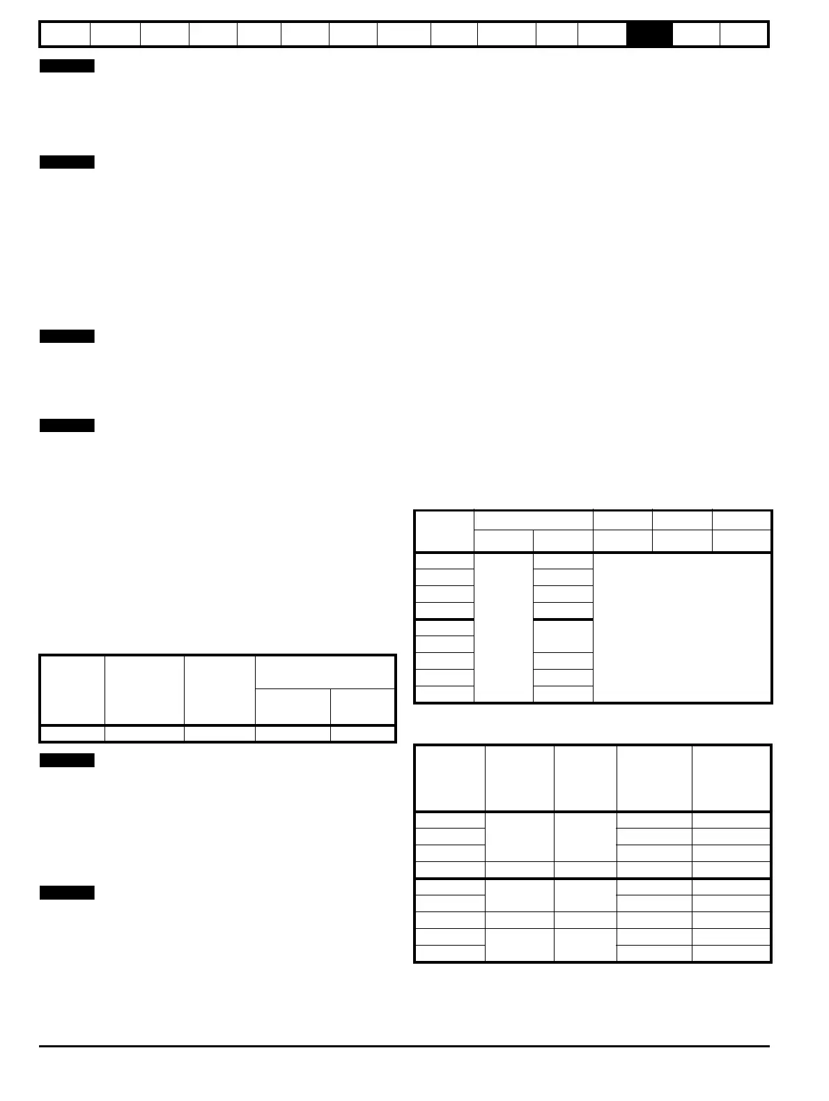
Table 13-21 Motor cable size and maximum lengths
13.1.28 Braking resistor values
Table 13-22 Minimum resistance and power ratings
* Resistor tolerance: ±10 %
Model
Fuse rating
IEC class gG
Fuse rating
class CC
Input cable size
AA
mm
2
AWG
All 20 20 4.0 12
Model
Output cable 6kHz 8kHz 12kHz
mm
2
AWG m m m
DST1201
0.75
24
50
DST1202 22
DST1203 20
DST1204 18
DST1401
24
DST1402
DST1403 22
DST1404 20
DST1405 18
Model
Minimum
resistance*
Peak
power
rating
Continuous
power rating
Average
power for
0.25s
Ω kW kW kW
DST1201
23 6.6
0.5 1.6
DST1202 1.2 3.5
DST1203 1.6 4.9
DST1204 16 9.3 2.3 7.0
DST1401
111 5.5
0.8 2.3
DST1402 1.4 4.1
DST1403 75 8.1 2.0 6.1
DST1404
28 21.7
3.0 9.0
DST1405 4.1 12.2

 Loading...


