Safety
Information
Product
information
Mechanical
installation
Electrical
installation
Getting
started
Basic
parameters
Running the
motor
Optimization
EtherCAT
interface
SMARTCARD
Operation
Onboard
PLC
Advanced
parameters
Technical
Data
Diagnostics
UL listing
information
Digitax ST User Guide 39
Issue: 5
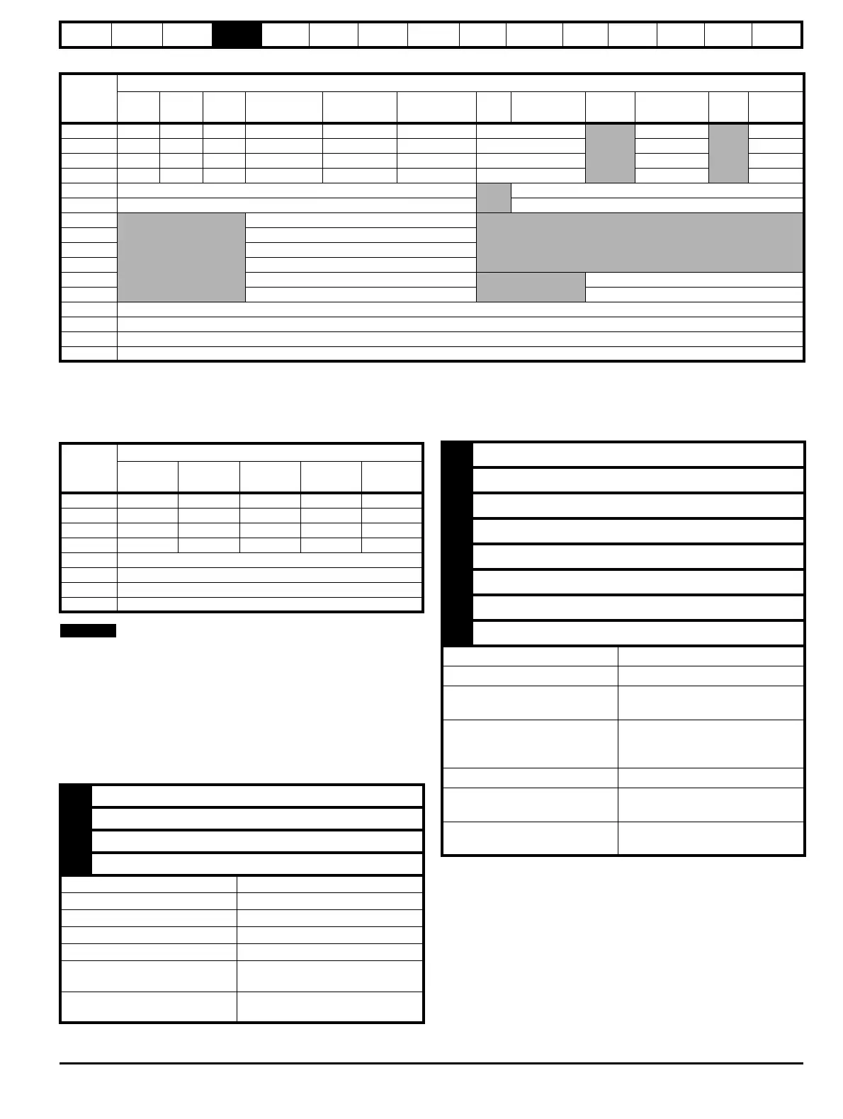
Table 4-20 Encoder In connector details
* Marker pulse is optional
** The encoder supply is selectable through parameter configuration to 5 Vdc, 8 Vdc and 15 Vdc
*** Terminal 15 is a parallel connection to T8 analog input 3. If this is to be used as a thermistor input, ensure that Pr 7.15 is set to ‘th.sc’ (7), ‘th’ (8)
or ‘th.diSP’ (9)
Table 4-21 Simulated encoder output connector details
SSI encoders typically have maximum baud rate of 500 kBaud. When a
SSI only encoder is used for speed feedback with a servo motor, a large
speed feedback filter (Pr 3.42) is required due to the time taken for the
position information to be transferred from the encoder into the drive.
The addition of this filter means that SSI only encoders are not suitable
for speed feedback in dynamic or high-speed applications.
Specifications
Feedback device connections
Ab, Fd, Fr, Ab.SErVO, Fd.SErVO and Fr.SErVO encoders
Term.
Setting of Pr 3.38
Ab
(0)
Fd
(1)
Fr
(2)
Ab.SErVO
(3)
Fd.SErVO
(4)
Fr.SErVO
(5)
SC
(6)
SC.HiPEr
(7)
EndAt
(8)
SC.EndAt
(9)
SSI
(10)
SC.SSI
(11)
1AFF A F F Cos
Cos Cos
2 A\ F\ F\ A\ F\ F\ Cosref Cosref Cosref
3 B D R B D R Sin Sin Sin
4 B\ D\ R\ B\ D\ R\ Sinref Sinref Sinref
5Z*
Encoder input - Data (input/output)
6 Z\* Encoder input - Data\ (input/output)
7
U
8U\
9V
10 V\
11 W
Encoder input - Clock (output)
12 W\ Encoder input - Clock\ (output)
13 +V**
14 0V common
15 th***
Shell 0V common
Term.
Setting of Pr 3.54
Ab
(0)
Fd
(1)
Fr
(2)
Ab.L
(3)
Fd.L
(4)
1A F F A F
2A\F\F\A\F\
3BDRBD
4B\D\R\B\D\
5Z*
6Z\*
14 0V
Shell 0V common
1 Channel A, Frequency or Forward inputs
2 Channel A\, Frequency\ or Forward\ inputs
3 Channel B, Direction or Reverse inputs
4 Channel B\, Direction\ or Reverse\ inputs
Type EIA 485 differential receivers
Maximum input frequency 500 kHz
Line loading <2 unit loads
Line termination components 120 Ω (switchable)
Working common mode range +12 V to –7 V
Absolute maximum applied
voltage relative to 0V
±25 V
Absolute maximum applied
differential voltage
±25 V
5 Marker pulse channel Z
6 Marker pulse channel Z\
7 Phase channel U
8 Phase channel U\
9 Phase channel V
10 Phase channel V\
11 Phase channel W
12 Phase channel W\
Type EIA 485 differential receivers
Maximum input frequency 512 kHz
Line loading
32 unit loads (for terminals 5 and 6)
1 unit load (for terminals 7 to 12)
Line termination components
120 Ω (switchable for terminals 5
and 6, always in circuit for terminals
7 to 12)
Working common mode range +12 V to –7 V
Absolute maximum applied
voltage relative to 0V
+14 V to -9 V
Absolute maximum applied
differential voltage
+14 V to -9 V

 Loading...


