Safety
Information
Product
information
Mechanical
installation
Electrical
installation
Getting
started
Basic
parameters
Running the
motor
Optimization
EtherCAT
interface
SMARTCARD
Operation
Onboard
PLC
Advanced
parameters
Technical
Data
Diagnostics
UL listing
information
40 Digitax ST User Guide
Issue: 5
SC, SC.HiPEr, EndAt, SC.EndAt, SSI and SC.SSI encoders
* Not used with EndAt and SSI communications only encoders.
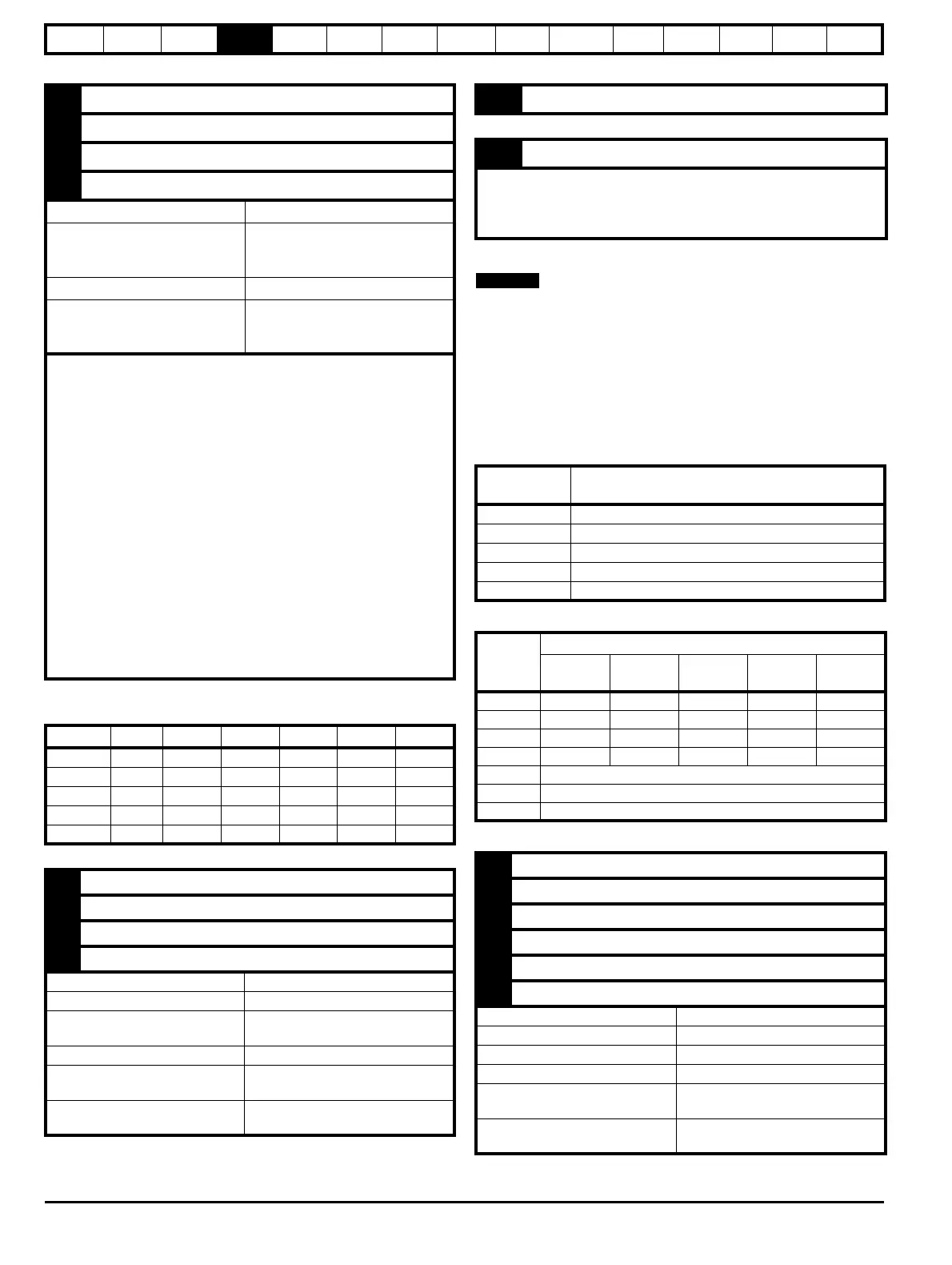
Table 4-22 Feedback resolution based on frequency and voltage level
** Not used with SC encoders.
*** Not used with SC and SC.HiPEr encoders.
4.16.2 Buffered encoder output
The buffered encoder output is sourced from the drive encoder input and
can be any incremental type or any SINCOS type (Note: - No output is
available if EndAt only or SSI communications only encoders are used).
If a SINCOS is used as the source the buffered output is derived from
the zero crossings of the sine waves and does not include interpolated
information. The buffered encoder output provides an output with
minimal delay from the drive encoder input (maximum delay is 0.5 µs). If
the source encoder does not have a marker pulse, then no marker pulse
can be obtained from the buffered encoder output.
Table 4-23 Encoder output types
Table 4-24 Buffered encoder connections
*Available when marker pulse input connected
1 Channel Cos*
2 Channel Cosref*
3 Channel Sin*
4 Channel Sinref*
Type Differential voltage
Maximum Signal level
1.25 V peak to peak (sin with regard
to sinref and cos with regard to
cosref)
Maximum input frequency See Table 4-22
Maximum applied differential
voltage and common mode
voltage range
±4V
For the SinCos encoder to be compatible with Digitax ST, the output
signals from the encoder must be a 1 V peak to peak differential voltage
(across Sin to Sinref and Cos to Cosref).
The majority of encoders have a DC offset on all signals. A number of
encoder manufactures typically have a 2.5 Vdc offset. The Sinref and
Cosref are a flat DC level at 2.5 Vdc and the Cos and Sin signals have
a 1 V peak to peak waveform biased at 2.5 Vdc.
Encoders are available which have a 1 V peak to peak voltage on Sin,
Sinref, Cos and Cosref. This results in a 2 V peak to peak voltage seen
at the drive's encoder terminals. It is not recommended that encoders of
this type are used with Digitax ST, and that the encoder feedback
signals should meet the above parameters (1 V peak to peak).
Resolution: The sinewave frequency can be up to 500 kHz but the
resolution is reduced at high frequency. Table 4-22 shows the number
of bits of interpolated information at different frequencies and with
different voltage levels at the drive encoder port. The total resolution in
bits per revolution is the ELPR plus the number of bits of interpolated
information. Although it is possible to obtain 11 bits of interpolation
information, the nominal design value is 10 bits.
Volt/Freq 1 kHz 5 kHz 50 kHz 100 kHz 200 kHz 500 kHz
1.2 11 11 10 10 9 8
1.0111110997
0.8101010987
0.610109987
0.4999876
5 Data**
6 Data\**
11 Clock***
12 Clock\***
Type EIA 485 differential transceivers
Maximum frequency 2 MHz
Line loading
32 unit loads (for terminals 5 and 6)
1 unit load (for terminals 11 and 12)
Working common mode range +12 V to –7 V
Absolute maximum applied
voltage relative to 0V
+14 V to -9 V
Absolute maximum applied
differential voltage
+14 V to -9 V
14 0V common
15 Motor thermistor input
This terminal is connected internally to terminal 8 of the signal
connector. Connect only one of these terminals to a motor thermistor.
Analog input 3 must be in thermistor mode, Pr 7.15 = th.SC (7), th (8) or
th.diSP (9).
Setting of
Pr 3.54
Description
Ab (0) Quadrature outputs
Fd (1) Frequency and direction outputs
Fr (2) Frequency and reverse outputs
Ab.L (3) Quadrature outputs with marker lock
Fd.L (4) Frequency and direction outputs with marker lock
Term.
Setting of Pr 3.54
Ab
(0)
Fd
(1)
Fr
(2)
Ab.L
(3)
Fd.L
(4)
1A F F A F
2A\F\F\A\F\
3BDRBD
4B\D\R\B\D\
5Z*
6Z\*
14 0V
1 A, F
2 A\, F\
3 B, D, R
4 B\, D\, R\
5 Z
6 Z\
Type EIA 485 differential transmitter
Max frequency 512 KHz
Max load capability 31 units
Working common mode range +12 V to -7 V
Absolute maximum applied
voltage relative to 0V
+14 V to -14 V
Absolute maximum applied
differential voltage
+14 V to -14 V

 Loading...


