Safety
Information
Product
information
Mechanical
installation
Electrical
installation
Getting
started
Basic
parameters
Running the
motor
Optimization
EtherCAT
interface
SMARTCARD
Operation
Onboard
PLC
Advanced
parameters
Technical
Data
Diagnostics
UL listing
information
Digitax ST User Guide 41
Issue: 5
4.16.3 Digitax ST Plus additional connections
Figure 4-18 Digitax ST Plus terminals view
The terminals are numbered from terminal 1 at the top, to terminal 13 at
the bottom as per the orientation shown in Figure 4-18. The terminal
functions are given in Table 4-25:
Table 4-25 Digitax ST Plus connector details
4.16.4 Digitax ST EZMotion additional connections
Figure 4-19 Digitax ST EZMotion terminals view
Table 4-26 Digitax EZMotion connector details
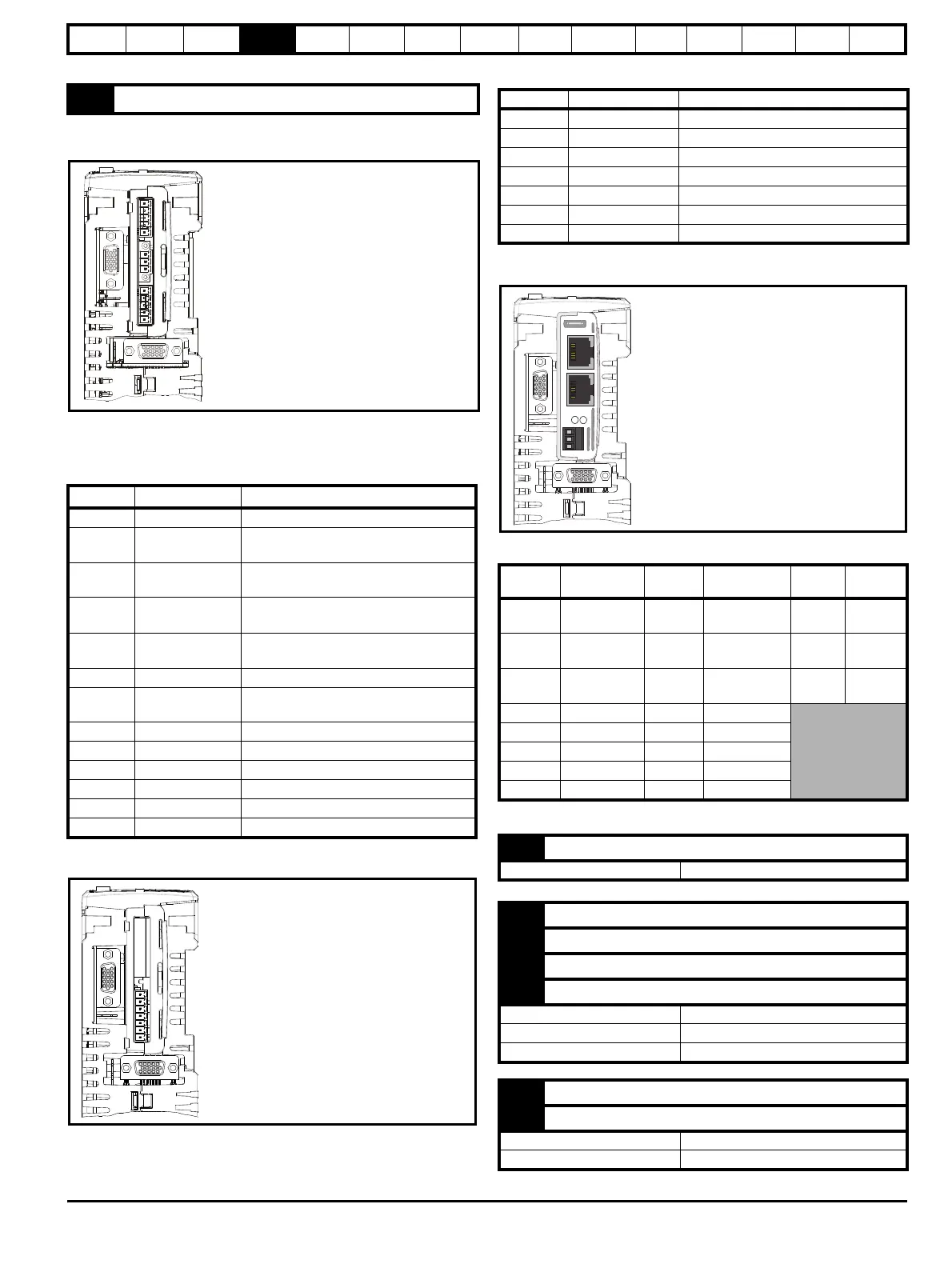
4.16.5 Digitax ST EtherCAT additional connections
Figure 4-27 Digitax ST EtherCAT terminals view
Table 4-20 Digitax EtherCAT connector details
14 0V common
Terminal Function Description
1 0V SC 0V connection for EIA-RS485 port
2/RX
EIA-RS485 Receive line (negative).
Incoming.
3RX
EIA-RS485 Receive line (positive).
Incoming.
4/TX
EIA-RS485 Transmit line (negative).
Outgoing.
5TX
EIA-RS485 Transmit line (positive).
Outgoing.
6 Fieldbus Type A Fieldbus Type data line
7
Fieldbus Type
Shield
Shield connection for Fieldbus Type
8 Fieldbus Type B Fieldbus Type data line
9 0V 0V connection for digital I/O
10 DI0 Digital input 0
11 DI1 Digital input 1
12 DO0 Digital output 0
13 DO1 Digital output 1
Connector specification:
Maximum size cable = 1.5 mm
2
Torque = 0.2 N m (1.8 lb in)
Connector specification:
Maximum size cable = 1.5 mm
2
Torque = 0.2 N m (1.8 lb in)
Terminal Function Description
1 0V common 0V common connection for digital I/O
2 Input 1 Digital input 1
3 Input 2 Digital input 2
4 Input 3 Digital input 3
5 Input 4 Digital input 4
6 Output 1 Digital output 1
7 Output 2 Digital output 2
Terminal
Function
(A - IN)
Terminal
Function
(B - OUT)
Digital
Inputs
Function
1 Transmit + 1 Transmit + 1
0V
Common
2 Transmit - 2 Transmit - 2
Digital
input 0
3 Receive + 3 Receive + 3
Digital
input 1
4 Not used 4 Not used
5 Not used 5 Not used
6 Receive - 6 Receive -
7 Not used 7 Not used
8 Not used 8 Not used
1 0V common
Function Common connection for Digital I/O
2 Input 1
3 Input 2
4 Input 3
5 Input 4
Input turn on voltage 15 Vdc ± 0.5 Vdc
Input voltage range 0 Vdc to +24 Vdc
Maximum input voltage + 30 Vdc
6 Output 1
7 Output 2
Output voltage Depends on 24 Vdc supply
Maximum output current 20mA total for both outputs
Connector specification:
Maximum size cable = 1.5mm
2
Torque = 0.2 N m (1.8 lb in)

 Loading...


