Safety
Information
Product
information
Mechanical
installation
Electrical
installation
Getting
started
Basic
parameters
Running the
motor
Optimization
EtherCAT
interface
SMARTCARD
Operation
Onboard
PLC
Advanced
parameters
Technical
Data
Diagnostics
UL listing
information
56 Digitax ST User Guide
Issue: 5
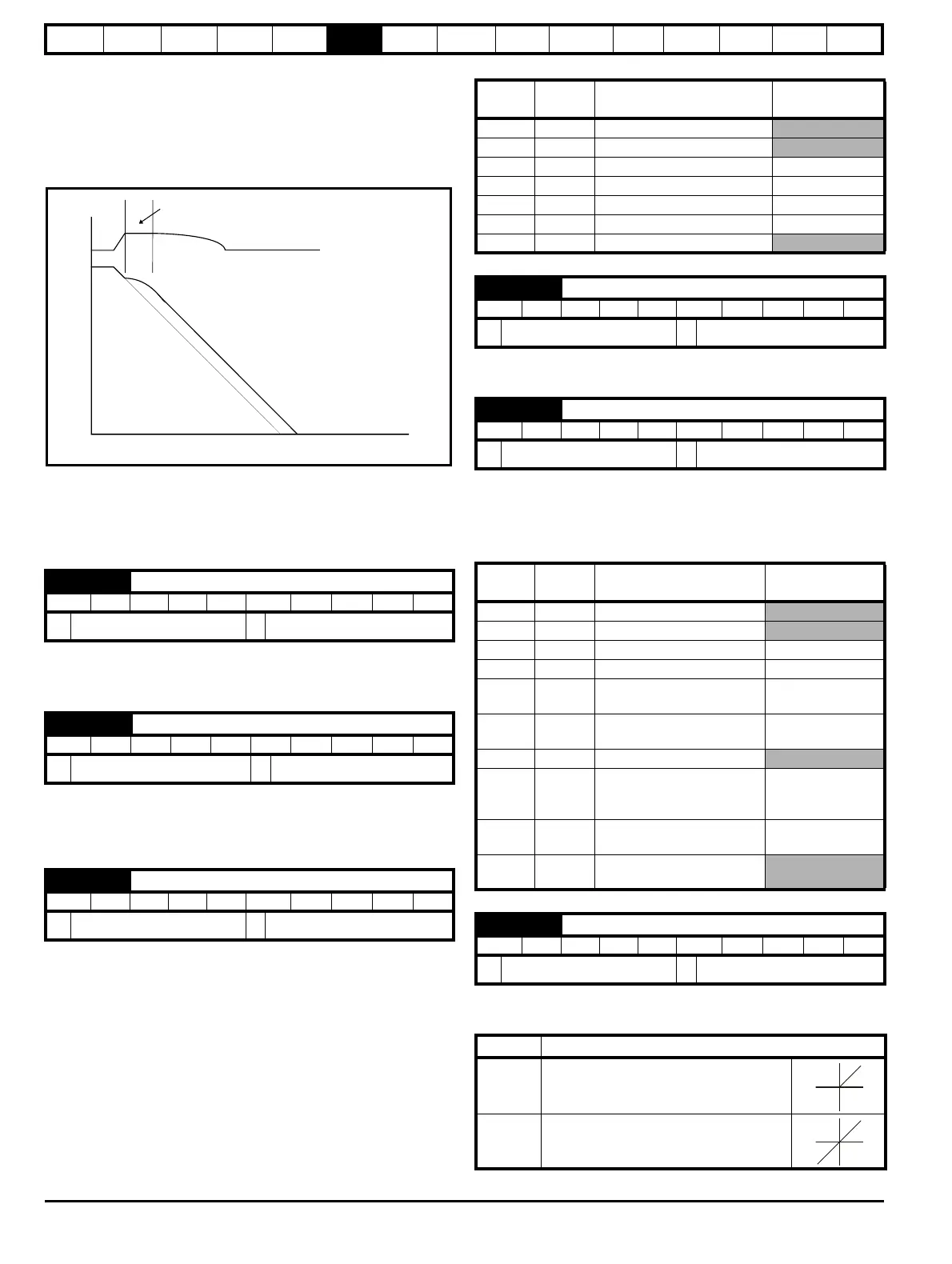
reaches the programmed deceleration rate the controller ceases to
operate and the drive continues to decelerate at the programmed rate. If
the standard ramp voltage (Pr
2.08
) is set lower than the nominal DC bus
level the drive will not decelerate the motor, but it will coast to rest. The
output of the ramp controller (when active) is a current demand that is fed
to the torque producing current controller (Servo mode). The gain of these
controllers can be modified with Pr
4.13
and Pr
4.14
.
2: Standard ramp with motor voltage boost
This mode is the same as normal standard ramp mode except that the
motor voltage is boosted by 20 %. This increases the losses in the
motor, dissipating some of the mechanical energy as heat giving faster
deceleration.
Setting Pr 0.16 to 0 allows the user to disable the ramps. This is
generally used when the drive is required to closely follow a speed
reference which already contains acceleration and deceleration ramps.
A first order filter, with a filter defined by Pr 0.17, is provided on the
current demand to reduce acoustic noise and vibration produced as a
result of position feedback quantization noise. The filter introduces a lag
in the speed loop, and so the speed loop gains may need to be reduced
to maintain stability as the filter is increased.
In modes 2 & 3 a current loop loss trip is generated if the current falls
below 3 mA.
In modes 2 & 4 the analog input level goes to 0.0 % if the input current
falls below 4 mA.
Pr 0.20 sets the destination of analog input 2.
In modes 2 & 3 a current loop loss trip is generated if the current falls
below 3 mA.
In modes 2 & 4 the analog input level goes to 0.0 % if the input current
falls below 4 mA.
Pr 0.22 determines whether the reference is uni-polar or bi-polar as
follows:
0.16 {2.02} Ramp enable
RW Bit US
Ú
OFF (0) or On (1)
Ö
On (1)
0.17 {4.12} Current demand filter
RW Uni US
Ú
0.0 to 25.0 ms
Ö
0.0
0.19 {7.11} Analog input 2 mode
RW Txt US
Ú
0 to 6
Ö
VOLt (6)
DC bus voltage
Motor Speed
Programmed
deceleration
rate
t
Controller
operational
Pr
value
Pr
string
Mode Comments
0 0-20 0 - 20 mA
1 20-0 20 - 0 mA
2 4-20.tr 4 - 20 mA with trip on loss Trip if I < 3 mA
3 20-4.tr 20 - 4 mA with trip on loss Trip if I < 3 mA
4 4-20 4 - 20 mA with no trip on loss 0.0 % if I ≤ 4 mA
5 20-4 20 – 4 mA with no trip on loss 100 % if I ≤ 4 mA
6 VOLt Voltage mode
0.20 {7.14} Analog input 2 destination
RW Uni DE PT US
Ú
Pr 0.00 to Pr 21.51
Ö
Pr 1.37
0.21 {7.15} Analog input 3 mode
RW Txt PT US
Ú
0 to 9
Ö
th (8)
Pr
value
Pr
string
Mode Comments
0 0-20 0 - 20 mA
1 20-0 20 - 0 mA
2 4-20.tr 4 - 20 mA with trip on loss Trip if I < 3 mA
3 20-4.tr 20 - 4 mA with trip on loss Trip if I < 3 mA
44-20
4 - 20 mA with no trip on
loss
0.0% if I ≤ 4 mA
5 20-4
20 - 4 mA with no trip on
loss
100 % if I ≤ 4 mA
6 VOLt Voltage mode
7th.SC
Thermistor mode with short-
circuit detection
Th trip if R > 3K3
Th reset if R < 1K8
ThS trip if R < 50R
8th
Thermistor mode with no
short-circuit detection
Th trip if R > 3K3
Th reset if R < 1K8
9 th.diSp
Thermistor mode with
display only and no trip
0.22 {1.10} Bipolar reference select
RW Bit US
Ú
OFF (0) or On (1)
Ö
OFF (0)
Pr 0.22 Function
0 Unipolar speed/reference
1 Bipolar speed/reference
 Loading...


